 EN
EN
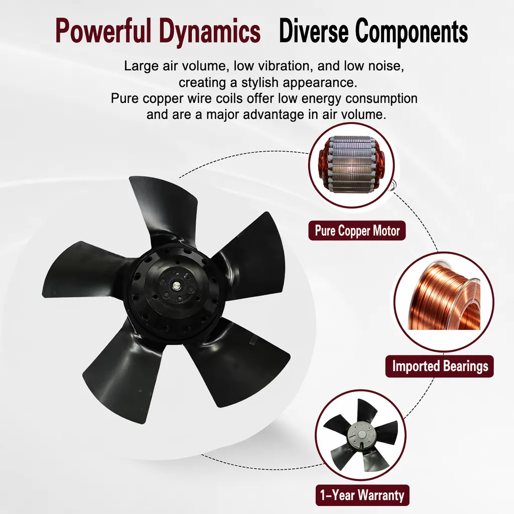
How Axial Flow Blower Deliver Stable Cold Air Flow for Battery Testing Laboratories
Battery testing laboratories operate under tight thermal management requirements that most industrial cooling scenarios rarely have to address. Whether cycling lithium-ion cells through SAE J2464 temperature protocols or holding test chambers at precisely 20°C for UL 1642 short circuit evaluations, the airflow system cannot be an afterthought. In my work supporting thermal system selection for industrial testing environments, I have found that the choice of an axial flow blower rather than a centrifugal or mixed-flow unit often proves to be the right starting point for battery lab cooling applications. The reasons are grounded in how axial flow aerodynamics interact with the specific demands of battery test chamber design.
Why Battery Testing Labs Have Demanding Airflow Needs
The thermal environment inside a battery testing laboratory is not simply about keeping equipment cool. Standards like SAE J2464 require temperature cycling between -40°C and 70°C with controlled ramp rates, while UL 1642 specifies heating tests that ramp from 20°C to 130°C at 5°C per minute. What connects these requirements is the need for repeatability: the airflow system must deliver consistent cold air at every stage of the test cycle, not just during steady-state operation.
This is where many engineers make a selection error. The datasheet shows airflow looks ideal under standard conditions, but in a battery test chamber where internal heat loads fluctuate rapidly during charge and discharge cycles, actual fan performance can show measurable deviation from rated output. The airflow system needs to compensate for load changes without introducing turbulence or velocity spikes that would compromise test cell uniformity.
There are three core airflow requirements in a well-designed battery test environment:
- Volume consistency: Sufficient airflow to remove the heat generated by cells under test without creating localized hot zones across the battery array.
- Velocity uniformity: Even distribution of cold air across all cells or modules being tested. Irregular airflow creates temperature gradients that affect test data reliability.
- Vibration minimization: Battery cell impedance measurements and other electrochemical tests are sensitive to mechanical vibration. The airflow system must not introduce mechanical disturbances.
How Axial Flow Blower Characteristics Align With These Requirements
An axial flow blower moves air parallel to its shaft axis, which produces a fundamentally different flow pattern than a centrifugal or radial fan. The airflow exits in the same direction it entered, with relatively low pressure rise and high volumetric capacity. For battery test chamber applications, this translates into several practical advantages, at least in configurations where the static pressure requirements of the chamber ductwork fall within the axial design's operating range.
The laminar-dominant flow pattern of an axial air mover allows cold air to travel across a battery array with greater uniformity than the turbulent discharge from a centrifugal unit. When you need temperature uniformity across a rack of test cells, the airflow path geometry and entry velocity matter far more than raw airflow figures. An axial blower's planar discharge profile suits inline flow arrangements commonly used in battery pack test fixtures.
Modern axial flow blowers equipped with BLDC or EC motor technology maintain consistent rotational speed regardless of supply voltage fluctuations or minor load changes on the system side. This speed stability directly translates to airflow stability, a meaningful advantage in battery test scenarios where the thermal load on the chamber varies continuously as cells move through charge, discharge, and rest phases. Something that is easy to underestimate until you measure it: even a small but consistent airflow fluctuation can introduce temperature drift across a test session, which matters for comparative cell testing.
The mechanical simplicity of the axial design, with a single rotating impeller and no scroll housing or inlet vanes to generate turbulent separation, results in lower structural vibration transmission to the test fixture. For labs running electrochemical impedance spectroscopy or precision voltage measurements alongside thermal cycling, this is worth factoring in carefully.
Selecting the Right Axial Flow Blower for Your Battery Lab Configuration
Not every axial flow blower is suited for every battery testing configuration. The selection decision depends on several interacting factors that go beyond airflow rating alone.
Static pressure matching: Battery test chambers with filtered inlet sections, baffles, or internal ducting to distribute air across cell arrays can create meaningful static pressure resistance. Axial blowers generally operate most efficiently at low-to-medium static pressure. If your chamber design creates higher resistance, a mixed-flow variant or ducted axial configuration may be required to maintain rated airflow delivery.
Speed control interface: For chambers that vary temperature setpoint during a test cycle, the blower needs to modulate airflow accordingly. EC motor-driven axial blowers accept 0-10V or PWM control signals that integrate directly with most test chamber controllers. This closed-loop speed adjustment ensures cold air delivery tracks the chamber's thermal demand rather than running at a fixed output that either under-cools during peak load or over-cools during rest phases.
Operating temperature range of the motor: Battery testing labs that perform low-temperature cycling, with some protocols going to -40°C, need a blower whose motor and bearing assembly is rated for the ambient conditions inside or adjacent to the chamber. Standard industrial ratings assume a 40°C maximum ambient; for cold-environment positioning, confirm the motor's minimum operating temperature and whether bearing lubrication is appropriate for the range.
Vibration grade and mounting: For high-precision testing, specify an axial blower with ISO-grade vibration rating and mount it using anti-vibration isolators. The impeller balance quality should be confirmed against the sensitivity requirements of the test instrumentation in your lab.
Practical Notes From Battery Lab Deployments
One observation from installations in battery research facilities: engineers frequently underestimate how much the inlet geometry of the blower mounting affects actual cold air distribution across the test array. Even a partially blocked inlet grille at the blower mounting panel can reduce effective airflow delivery to the cell array by a meaningful margin, something that does not appear in datasheet specs but shows up as temperature non-uniformity during commission testing.
For new battery lab designs, it is worth running a basic airflow simulation of the chamber interior before finalizing blower position and quantity. In most rectangular cell array configurations, two smaller axial flow blowers in a push-pull arrangement provide better uniformity than a single high-capacity unit, particularly for arrays longer than 600 mm along the airflow axis. This kind of system-level thinking tends to produce more reliable test environments than selecting the highest airflow blower available.
Lebisen's axial fan product range includes EC and BLDC motor variants with the speed control interfaces and vibration grades appropriate for controlled test environments. For trading companies supplying laboratory equipment integrators or test system builders in Europe, North America, or South America, axial blower selection for battery test applications is a technically specific requirement that benefits from supplier pre-sales technical support. For product specifications and application guidance, visit Guangdong Lebisen Fan Co., Ltd.
Summary: What Stable Cold Air Flow Actually Requires
Delivering stable cold air flow in a battery testing laboratory comes down to matching the axial flow blower's operating characteristics to the chamber's airflow path geometry, static pressure budget, and thermal load profile, not simply selecting the highest CFM unit available. The axial design's planar, relatively laminar discharge suits cell array layouts where uniformity matters. EC and BLDC motor-driven axial air mover units add the speed stability and modulation capability that battery testing protocols demand across wide temperature ranges. Attention to mounting, vibration isolation, and inlet geometry then translates those aerodynamic advantages into consistent, repeatable test conditions throughout the test cell's service life.