 EN
EN

How Backward Curved Centrifugal Blower Impeller Design Influences Overall Fan Efficiency
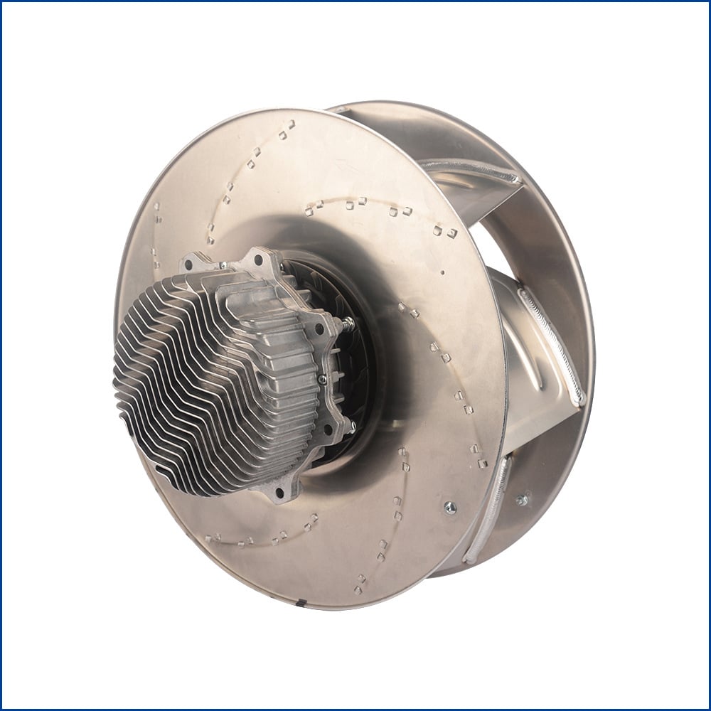
When evaluating centrifugal blowers for industrial applications, the conversation often starts and ends with airflow ratings and static pressure numbers. Those metrics matter — but they don't tell you much about why one unit performs better than another under the same load conditions. A significant portion of fan efficiency is determined before the motor is selected or the housing is sized — it starts with the geometry of the backward curved centrifugal blower impeller.
This article examines the specific design parameters that govern impeller aerodynamic behavior and explains how each one contributes to — or detracts from — overall fan efficiency. The goal is not to fixate on datasheet numbers, but to understand the underlying mechanisms that produce those numbers in the first place.
What Makes a Backward Curved Impeller Different
A centrifugal fan impeller can be designed with forward curved, radial, or backward curved blades. In backward curved designs, the blades lean away from the direction of rotation. As a result, air exits the impeller at a more controlled trajectory, with less tangential velocity component and more of the energy converted directly into static pressure.
The practical outcome is that backward curved impellers move air at a given static pressure level while consuming less power than equivalent forward curved designs. The blade geometry reduces the degree to which kinetic energy must be recovered in the volute, making the overall pressure conversion more aerodynamically efficient. That efficiency advantage is what makes backward curved configurations the preferred choice for industrial and HVAC applications where continuous-duty energy consumption matters.
Key Design Parameters That Affect Efficiency
The performance of a backward curved centrifugal blower impeller is shaped by several interrelated geometric parameters. Changing any one of them shifts the entire operating characteristic of the fan — including peak efficiency, curve shape, and stall behavior.
Blade Exit Angle
The blade exit angle (also referred to as the outlet angle) is measured between the blade tangent at the outer diameter and the tangential direction of rotation. In backward curved designs, this angle is typically set below 90 degrees — often in the range of 15 to 45 degrees from the radial plane. The smaller this angle, the more "backward" the blade lean.
A lower exit angle reduces the swirl component of the exiting airflow, which is the portion of kinetic energy that would otherwise need to be recovered as pressure in the housing. Less energy wasted in swirl recovery means higher hydraulic efficiency at the impeller level. However, reducing the exit angle too aggressively narrows the operating range of the fan and can shift the peak efficiency point toward lower flow rates, which may not suit all system requirements.
Blade Count
The number of blades in the impeller influences both efficiency and noise behavior. More blades provide greater guidance to the airflow through the impeller passages, reducing flow separation and turbulence losses. Research modeling backward curved impellers has consistently shown that blade count has a measurable impact on total pressure rise and aerodynamic efficiency — underblade passages that are too wide lead to flow instability, while excessively narrow passages increase friction losses.
In practice, most industrial backward curved centrifugal fan impellers are designed with blade counts in the range of 8 to 16 blades, depending on diameter, target flow rate, and acoustic requirements. The optimal number is specific to the design operating point and requires balancing hydraulic efficiency against manufacturability and vibration characteristics.
Blade Width and Chord Length
Blade width (the axial depth of the impeller) determines how much flow the fan can handle at a given rotational speed and diameter. A narrower impeller tends to produce higher static pressure at lower flow volumes; a wider impeller shifts the characteristic curve toward higher flow rates. The chord length — the effective length of the blade from leading edge to trailing edge — affects how much turning work the blade does on the airflow and influences boundary layer development along the blade surface.
For a high efficiency backward curved centrifugal blower, the chord-to-pitch ratio of the blades is often optimized through computational fluid dynamics (CFD) simulation to minimize boundary layer separation while maintaining the desired pressure-flow characteristic. Small deviations from the intended geometry, whether from manufacturing tolerances or material distortion, can meaningfully shift where on the efficiency curve the impeller actually operates in service.
How Impeller Geometry Shapes the Fan Performance Curve
One of the less-discussed advantages of backward curved impeller design is the characteristic shape of the resulting fan curve. Backward curved impellers produce a non-overloading power curve: as flow rate increases beyond the design point, the power consumption of the fan does not rise steeply. This contrasts with forward curved designs, where high flow conditions can cause the motor to be overloaded.
The non-overloading characteristic is a direct result of the exit angle geometry described above. At high flow rates, the backward curved blade geometry naturally limits the amount of work done on the air, which constrains power draw. For system designers and specifiers, this provides an important safety margin: the motor can be sized closer to the actual design point without risk of overload if the system resistance drops unexpectedly.
The efficiency island (the region of peak efficiency) on the fan curve is typically broader and more stable for backward curved impellers than for radial or forward curved alternatives. This means that real-world operating points can deviate somewhat from the design point without causing dramatic efficiency losses, which matters in systems where ductwork resistance changes seasonally or with process variations.
Beyond the Impeller: System-Level Efficiency Considerations
The impeller is, in practice, just one component within a larger aerodynamic system. Even a well-designed backward curved centrifugal blower impeller will underperform if the surrounding system (inlet geometry, volute casing, motor selection, and installation conditions) is not well matched to the impeller's operating requirements.
Inlet conditions have a particularly strong influence. Disturbed inlet flow, caused by obstructions, sharp bends immediately upstream, or inadequate inlet clearance, can reduce effective impeller efficiency by several percentage points even if the impeller itself is geometrically correct. The volute casing must be dimensioned to match the velocity triangle at the impeller outlet; a mismatched volute increases pressure losses in the casing and reduces the static pressure recovered from the kinetic energy leaving the impeller.
Motor efficiency is the other major variable. Pairing a high-efficiency backward curved impeller with an EC (electronically commutated) motor, rather than a conventional AC induction motor, allows the entire fan unit to benefit from variable-speed operation and high part-load efficiency. The impeller's favorable non-overloading characteristic complements the speed-variable control profile of EC drive systems.
Selecting a High Efficiency Backward Curved Centrifugal Blower
When evaluating options for a high efficiency backward curved centrifugal blower, the impeller design is a central factor — but it must be assessed alongside the complete system specification. Key questions to consider include:
- What is the actual operating point (airflow and static pressure at the installation), and where does it fall on the fan curve relative to the peak efficiency island?
- Has the impeller been designed and verified for that operating point specifically, or is it a standard catalog product being applied outside its intended range?
- How does the inlet and outlet configuration of the installation affect the real-world efficiency relative to the tested condition?
- What are the duty cycle and load variation requirements, and does the non-overloading characteristic provide adequate operating margin?
Published efficiency ratings are typically measured under standardized laboratory conditions with well-controlled inlet flow. In real installations, these conditions are rarely met exactly. A fan rated at a high efficiency point on its datasheet may operate meaningfully below that value if the installed conditions differ from the test setup. Understanding the impeller design principles helps in evaluating how sensitive a particular fan will be to these installation deviations.
Summary
The efficiency of a centrifugal blower system is substantially determined by the geometry of its impeller. For backward curved designs, the blade exit angle, blade count, and blade width interact to set the shape of the fan curve, the location of the peak efficiency island, and the non-overloading characteristic that makes these units well-suited to variable-load industrial applications. Optimizing these parameters is not a simple exercise — it requires balancing aerodynamic efficiency against operating range, manufacturability, and acoustic constraints.
For applications where continuous-duty energy efficiency and stable operation across varying system resistance are priorities, a well-engineered backward curved centrifugal blower impeller remains one of the most effective design choices in industrial air movement. The difference between a standard impeller and an optimized one is not immediately visible on a specification sheet, but it shows up consistently in long-term operating energy costs and system reliability.