EN
EN
What filter matching rule for dust proof cabinet cooling fan operating in cement factories
2026/09/30
Cement cabinets choke on dust. Learn the filter rule for an industrial cabinet cooling fan: G4/F7 media, IP rating, and pre-filter care.

2026/09/10
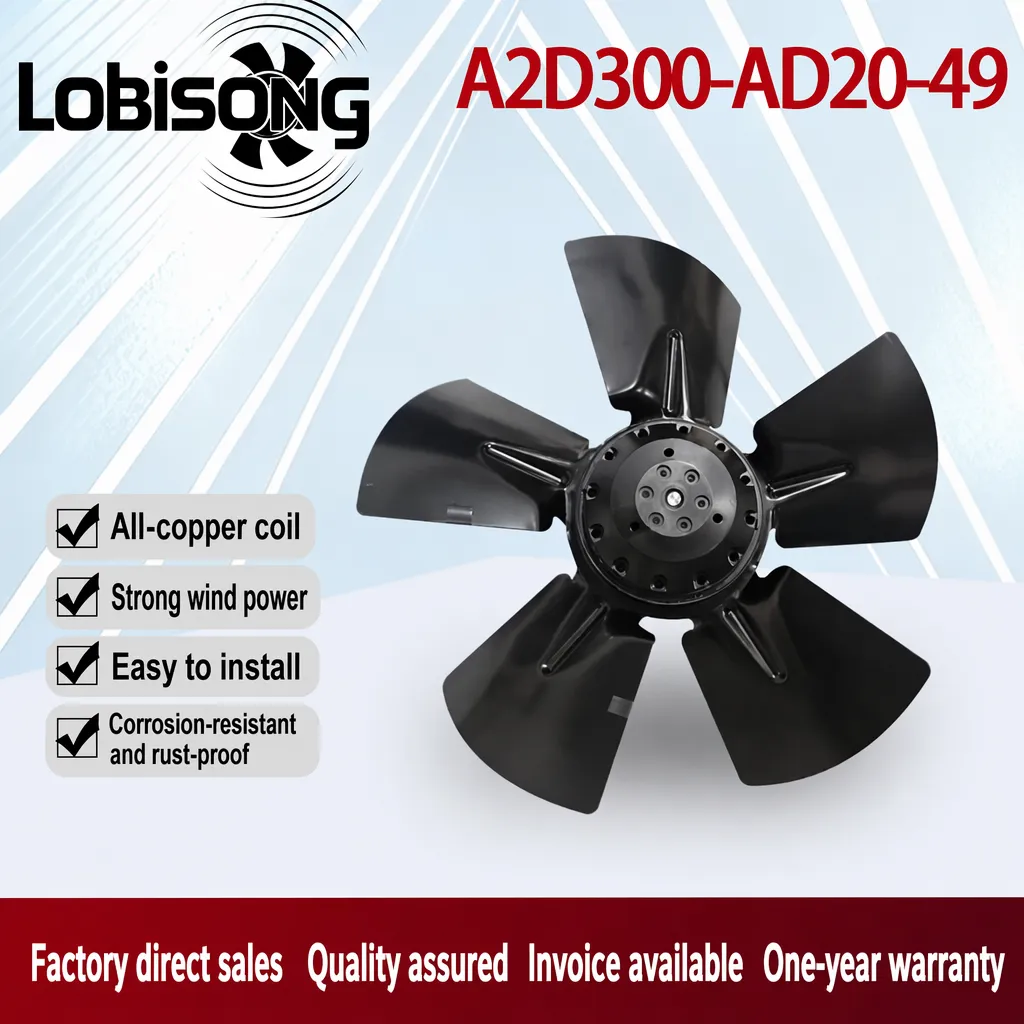
Modern automation panels pack PLCs, servo drives and relay modules onto crowded DIN rails, and the heat they release has nowhere to escape. A compact equipment cooling fan becomes the practical answer when enclosure volume is small but component density keeps rising. Without active airflow, internal temperatures climb until thermal trip events interrupt production.
A compact equipment cooling fan works by replacing still air with a continuous stream that carries heat away from hot component surfaces. Semiconductor devices on a PLC or servo drive shed energy as thermal resistance builds between the junction and the surrounding air. Forced convection lowers that resistance because moving air strips the warm boundary layer faster than natural buoyancy ever could. The impeller accelerates air across heat sinks and vent slots, so the hottest points—usually near power supplies and IGBT blocks—cool first. Sizing still matters: a small axial model with weak static pressure may stall behind closely stacked devices, while a unit matched to the enclosure airflow path sustains steady ventilation.
Natural convection relies on warm air rising and cooler air sinking, a slow cycle that works only for low-power enclosures with generous vent area. Miniature control cabinets rarely offer that luxury. Dense rows of PLC modules and servo drives block the vertical thermal column, trapping heat between metal surfaces. As internal temperature rises, the available temperature difference driving natural flow shrinks, so the cooling effect flattens exactly when needed most. Dust and cable bundles further restrict the free opening. At that point only forced convection from an active fan can maintain a safe thermal margin. Adding a compact equipment cooling fan converts that failing passive loop into steady forced convection, restoring the thermal margin.
A reliable airflow path starts with a clear intake low on the enclosure and an exhaust high on the opposite side, so warm air leaves near the top. The fan should pull cooler room air through a filtered inlet and push heated air past the modules, not recirculate it. Filter screens protect the impeller and motor winding from conductive dust, while a sealed bearing house keeps the ball bearing quiet. Cable trays and DIN rails must not block the stream; a clear lane between rows lets air reach every device back. In a narrow cabinet, a compact centrifugal or crossed-flow unit directs air sideways along the rail. Choosing a compact equipment cooling fan with a sealed ball bearing house keeps the airflow path clean and quiet over long runs.
Cubic feet per minute (CFM) describes total air volume, but static pressure decides whether that volume reaches the back of a crowded module array. Tightly packed DIN-rail devices act like a flow restriction; an axial fan rated for high free-air CFM may collapse once it meets that resistance. A compact equipment cooling fan chosen for adequate static pressure sustains airflow through the gaps instead of stalling. Specifiers should read the fan curve and pick a point where delivery and pressure both match the real restriction. Undersizing static pressure leaves hot pockets; oversizing wastes energy.
Thermal resistance, expressed as °C per watt, shows how much temperature rises for each watt a module dissipates. A continuous duty cycle near a hot wall demands a fan rated for constant run, not an intermittent unit. Brushless DC models with copper motor windings hold performance across long cycles and pair well with a speed-control module. CE and UKCA documentation matters for European and UK shipments, so confirm compliance before procurement. A compact equipment cooling fan specified from this heat-load math avoids both under-cooling and wasteful overspecification.
Good spacing is free cooling. Leaving a gap above power modules and between PLC rows lets air sweep each surface instead of pooling heat. Mount the fan on a rigid panel using vibration-dampening grommets, and orient the airflow path so it crosses—not parallels—the heat sources. Routine maintenance keeps performance: inspect filter screens monthly in dusty sites, clear cable obstructions, and listen for bearing noise that signals wear. A thermal check during commissioning confirms the layout works; a follow-up after three months catches drift. IP44 or IP54 ingress protection suits most control cabinets, while outdoor skids may need higher ratings.
A packaging line suffered frequent servo drive faults each summer, traced to a sealed panel holding a PLC, two drives and a switched-mode supply. Natural convection through small side vents could not keep pace, and the enclosure temperature approached the trip limit. The workshop added a filtered compact equipment cooling fan drawing room air across the DIN rail and exhausting through the top, with cable management moved to open the lane. After commissioning, peak temperature dropped and thermal trip events stopped during full-duty operation. The retrofit needed no cabinet enlargement and kept the existing components. It shows how a modest forced-convection upgrade resolves heat problems that passive design cannot.
Start by listing every heat-producing module and its wattage, then sum the load and read the enclosure's free vent area. Choose a fan whose curve delivers enough CFM at the expected static pressure, and prefer ball bearing construction for continuous duty. Verify ingress protection suits the site, confirm CE or UKCA marks for the target market, and check that the impeller and motor winding materials match the duty. During installation, keep the airflow path unobstructed and label intake versus exhaust. A compact equipment cooling fan earns its place only when sized, positioned and maintained against the real restriction, not against a catalog number alone.
How does forced convection cool a PLC module faster than natural airflow? Answer: Forced convection uses a moving air stream to strip the warm boundary layer from component surfaces, so heat leaves the PLC junction far quicker than warm air rising on its own. Natural convection depends on buoyancy and slows as the temperature difference shrinks. A driven airflow keeps the thermal resistance low across the whole duty cycle, holding the module below its trip limit even under peak load.
What static pressure is needed when DIN-rail modules sit close together? Answer: Tightly packed DIN-rail modules behave like a flow restriction, so an axial fan with high free-air CFM may collapse once it meets that resistance. The required static pressure depends on open vent area, filter resistance and cable fill inside the enclosure. Reading the fan curve at the real restriction shows whether delivery holds. Undersized pressure leaves hot pockets near the back row, while a properly matched fan sustains airflow through every gap.
Where should the fan sit so air reaches every control module? Answer: Place the intake low and the exhaust high on opposite sides, then run the airflow path across—not parallel to—the heat sources. Leave a clear lane between PLC rows and move cable trays off the stream. A compact equipment cooling fan mounted to pull air along the DIN rail sweeps each device surface instead of pressurizing dead space. Label intake and exhaust grilles so later service keeps the correct direction.
Can a brushless DC fan run continuously inside a sealed cabinet? Answer: Brushless DC fans with copper motor windings suit continuous duty because they hold speed and efficiency across long cycles without the wear of brushed commutation. Pairing the unit with a speed-control module trims energy during part-load periods. Confirm the ingress protection rating matches the site, and check CE or UKCA marks for the target market. Routine filter checks keep the airflow steady and protect the ball bearing from dust.
Why does spacing between modules affect cooling performance? Answer: Gaps above power modules and between PLC rows let air sweep each surface instead of pooling heat in dead corners. Dense stacking blocks the vertical thermal column and raises thermal resistance, so the same fan moves less effective air. Good spacing is essentially free cooling that lowers the required fan capacity. During commissioning, a thermal check confirms the layout works, and a follow-up after three months catches any drift from added cables.
2026/09/30
Cement cabinets choke on dust. Learn the filter rule for an industrial cabinet cooling fan: G4/F7 media, IP rating, and pre-filter care.

2026/10/07
Right wall-mount height for an industrial axial exhaust fan: room volume, free clearance, brackets, and recirculation control.

2026/10/08
An ec motor fan links to BMS via Modbus, 0-10V and PWM for demand-based cooling, energy scheduling and automatic sensor-driven speed control.
2026/10/06
A radial exhaust fan removes grease, fumes, and odors from food-processing workshops with capture velocity and hygienic washdown design.
2026/10/05
Learn antistatic treatment for industrial cabinet cooling fan in electronics workshops—ESD-safe housing, ionizable plastics, and cleanroom compatibility.
2026/10/04
Discover how a brushless dc servo delivers precise wind speed control for laboratory cooling fans with closed-loop PID feedback and laminar airflow.