 EN
EN
How Industrial Axial Fan 24 Inch Realize Wide Range Air Supply for Large Factory Workshops
When you're responsible for ventilation in a large factory workshop, one of the more persistent challenges is getting consistent airflow across the entire floor area, not just near the intake points. A well-chosen axial fan 24 inch can do considerably more than exhaust stale air from a single zone. Under the right conditions, it works as a primary driver of wide-area air circulation, provided the installation approach matches the space geometry and production environment.
This article examines the technical mechanisms that allow an axial fan 24 inch to cover large spaces effectively, and what system-level factors determine whether that potential is realized in practice.
Understanding the Airflow Mechanics of a 24-Inch Axial Fan
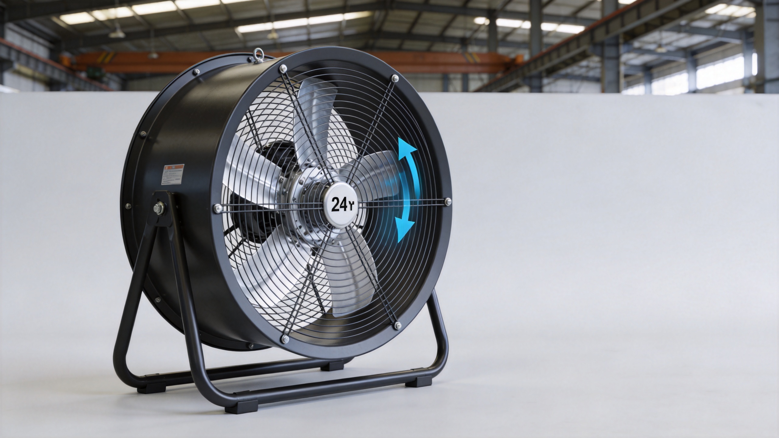
The impeller diameter of 24 inches (approximately 600mm) occupies a useful middle ground in industrial fan sizing. At this diameter, a 2HP axial fan typically delivers between 8,500 and 10,000 CFM of airflow, enough to serve as a primary ventilation unit in spaces up to roughly 5,000 to 8,000 square feet per installation point, depending on ceiling height and air change requirements.
What enables wide-range coverage is not raw CFM output alone. The throw distance, meaning the effective horizontal or vertical distance the discharged air travels before dissipating, depends on blade pitch angle, tip speed, and the discharge velocity at the fan outlet. A properly configured industrial axial fan 24 inch with a steeper blade angle generates higher velocity air that carries further into the workshop space, reaching areas that wall-mounted exhaust fans at lower velocity would not effectively serve.
Factory buildings ordinarily require 2 to 4 air changes per hour under standard conditions, rising to 10 to 15 ACH in environments with fumes, heat load, or moisture. Meeting the higher end of this range in a large workshop requires both adequate total CFM and effective air distribution. These are the two criteria that shape how large axial fans should be selected and positioned.
Key Technical Factors That Determine Coverage Breadth
Blade Angle and Pitch Adjustability
The blade pitch angle of an industrial axial fan controls the trade-off between airflow volume and static pressure. For open workshop environments with minimal ducting, a higher pitch angle increases volumetric output. For installations involving duct connections or recirculation paths, a lower pitch angle maintains pressure without overloading the motor. An axial fan 24 inch with adjustable pitch gives procurement engineers more flexibility when the workshop layout changes or when the production process introduces new heat or contaminant sources.
Rotational Speed and Motor Rating
At 1,450 RPM, a common operating speed for 50Hz industrial axial fans in this size range, a 24-inch unit delivers its rated airflow with a workable balance between throw distance and noise level. Higher RPM variants exist, though the noise increase is noticeable in occupied factory environments. It is worth checking whether the manufacturer's rated performance data is measured under standardized test conditions, since discrepancies between lab ratings and actual site performance remain a recurring concern in industrial fan procurement.
Motor Enclosure and Operating Environment
Large factory workshops vary considerably in their operating conditions. Ordinary assembly areas differ from foundries or chemical processing floors in terms of ambient temperature, particulate loading, and humidity. Industrial large axial fans used in standard production environments typically carry rated operating temperature ranges from approximately -18°C to 93°C. For environments with elevated heat loads or corrosive atmospheres, motor enclosure rating and materials of construction need closer evaluation before specifying a 24-inch unit.
Placement Strategies for Wide-Area Coverage
Even a well-specified axial fan 24 inch covers a limited zone if installed without regard to airflow distribution. A common mistake in large workshop ventilation design is treating each fan as an independent exhaust point rather than as part of a coordinated flow path.
- Cross-ventilation layout: Positioning intake and exhaust fans on opposing walls creates a pressure differential that drives air across the full width of the workshop. In a 50-meter-wide building, a single row of axial fans on each side may not be sufficient without intermediate circulation units to prevent dead zones in the center.
- Elevation and angle: Mounting axial fan 24 inch units at an elevated position and directing discharge airflow slightly downward toward the work floor improves occupant-level air movement without excessive turbulence near equipment or open materials.
- Spacing and grid arrangement: For very large workshops exceeding 10,000 square feet, a grid arrangement of fans with overlapping airflow envelopes avoids localized high-velocity zones and supports more consistent coverage. The spacing between units should account for the effective throw distance of the selected fan model.
System-Level Coordination for Large Workshops
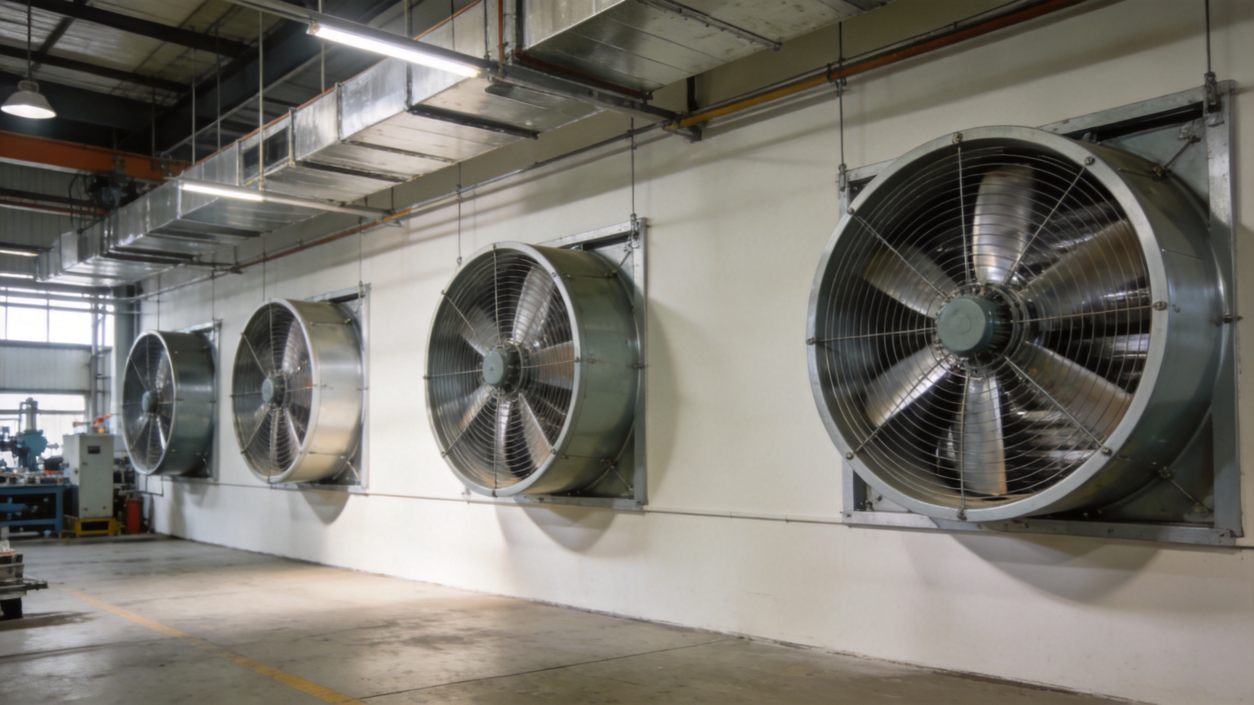
Moving from single-component thinking to system-level planning is where many factory ventilation projects either succeed or fall short. An individual axial fan 24 inch may perform exactly to its rated specification while still leaving significant portions of the workshop with inadequate air movement, because the surrounding airflow paths were not designed to support wide distribution.
Coordinating multiple large axial fans through staged activation, variable-speed control, or time-sequenced operation can improve coverage uniformity noticeably. EC (electronically commutated) motor variants offer variable-speed adjustment that allows facility managers to modulate airflow in response to production load changes, ambient temperature shifts, or occupancy patterns. This reduces energy consumption at partial load while maintaining adequate ventilation when full-capacity air supply is required.
Lebisen offers both AC and EC axial fan variants in this size range, supplying trading companies and system integrators who need consistent performance data, CE compliance documentation, and the ability to consolidate procurement across multiple fan specifications. For large factory workshop projects involving multiple installation points, consolidating the fan specification to a single supplier reduces the risk of inter-unit performance inconsistency.
Common Sizing and Selection Mistakes to Avoid
Selecting an axial fan 24 inch based on rated CFM without reviewing the operating point on the fan's performance curve is a common oversight. At the installation's actual static pressure, which may differ from the zero-static-pressure rating due to ductwork, grilles, or restricted intake paths, the delivered airflow will be lower than the catalogued figure. Reviewing the fan curve before finalizing the selection prevents under-sizing and the need for retrofit additions after commissioning.
Similarly, assuming that a higher-power motor automatically translates to better coverage in an open workshop can lead to unnecessary cost and noise. A correctly specified standard-efficiency unit, properly positioned, often outperforms an over-powered unit installed at a suboptimal location.
Conclusion
The ability of an industrial axial fan 24 inch to achieve wide-range air supply in large factory workshops depends on more than its nameplate airflow rating. Blade pitch, throw distance, motor type, placement strategy, and coordination with adjacent units collectively determine whether the installation meets the workshop's air change requirements uniformly across the floor area. Taking a system-level approach to fan selection, rather than evaluating each unit in isolation, is the most reliable path to consistent and efficient ventilation in large industrial spaces.
For procurement teams sourcing large axial fans for multi-point workshop installations, ensuring that the supplier can provide verified performance data, appropriate motor enclosure ratings, and EC variants for variable-speed integration will reduce both selection risk and long-term operating cost.