 EN
EN
How Professional BLDC Fan Driver Stabilizes Operation of 48V Brushless DC Motor Cooling Fan Sets
As someone who has evaluated industrial cooling systems across telecom equipment rooms and factory automation cabinets over many years, I've recognized a recurring pattern that still catches system integrators off guard: treating the fan and the motor as separate procurement decisions instead of one integrated thermal system. When a 48v brushless dc motor cooling fan set starts running erratically — hunting at partial load, surging under thermal changes, or losing synchronization on startup — the root cause is rarely the motor windings or the fan blades themselves. More often than not, it traces back to the driver.
A professional BLDC fan driver isn't simply a power delivery circuit. It's the control layer that keeps the entire cooling fan set operating in stable, predictable conditions across the conditions that a 48V system encounters in real service.
Why 48V Brushless DC Motor Cooling Fan Sets Need a Dedicated Driver
Most technical content on the subject focuses on 12V or 24V ceiling fan implementations. Those systems are relatively forgiving: lower supply voltage means less back-EMF to manage during commutation, smaller energy spikes at rotor position transitions, and wider timing tolerances in the control firmware. A 48v brushless dc motor operates in a different electrical regime with higher demands on the driver's control precision.
At 48V nominal, the motor generates proportionally higher counter-electromotive force as rotor speed increases. If the driver's commutation logic doesn't accurately track rotor position — through Hall-effect sensors or sensorless back-EMF zero-crossing detection — each phase transition becomes a source of torque ripple. In a cooling fan set where consistent airflow directly determines the temperature of the protected equipment, that ripple shows up as speed fluctuation, audible noise, and accelerated bearing wear.
Three stability challenges surface consistently in 48V cooling fan applications:
- Load transients during thermal ramp-up: Sudden thermal loads request higher speed. Poorly timed commutation during acceleration can cause phase lock loss, resulting in stall or speed undershoot before recovery.
- Voltage ripple on the 48V supply bus: Telecom and industrial 48V systems carry ripple from shared DC bus loads. A controller without adequate input filtering translates that ripple into PWM instability and downstream speed variation at the fan.
- Thermal derating of the motor itself: As the cooling fan permanent magnet bldc motor operates at high load over extended periods, winding resistance increases and the back-EMF constant shifts slightly. Controllers without real-time parameter adaptation respond with incorrect torque delivery, compounding speed instability.
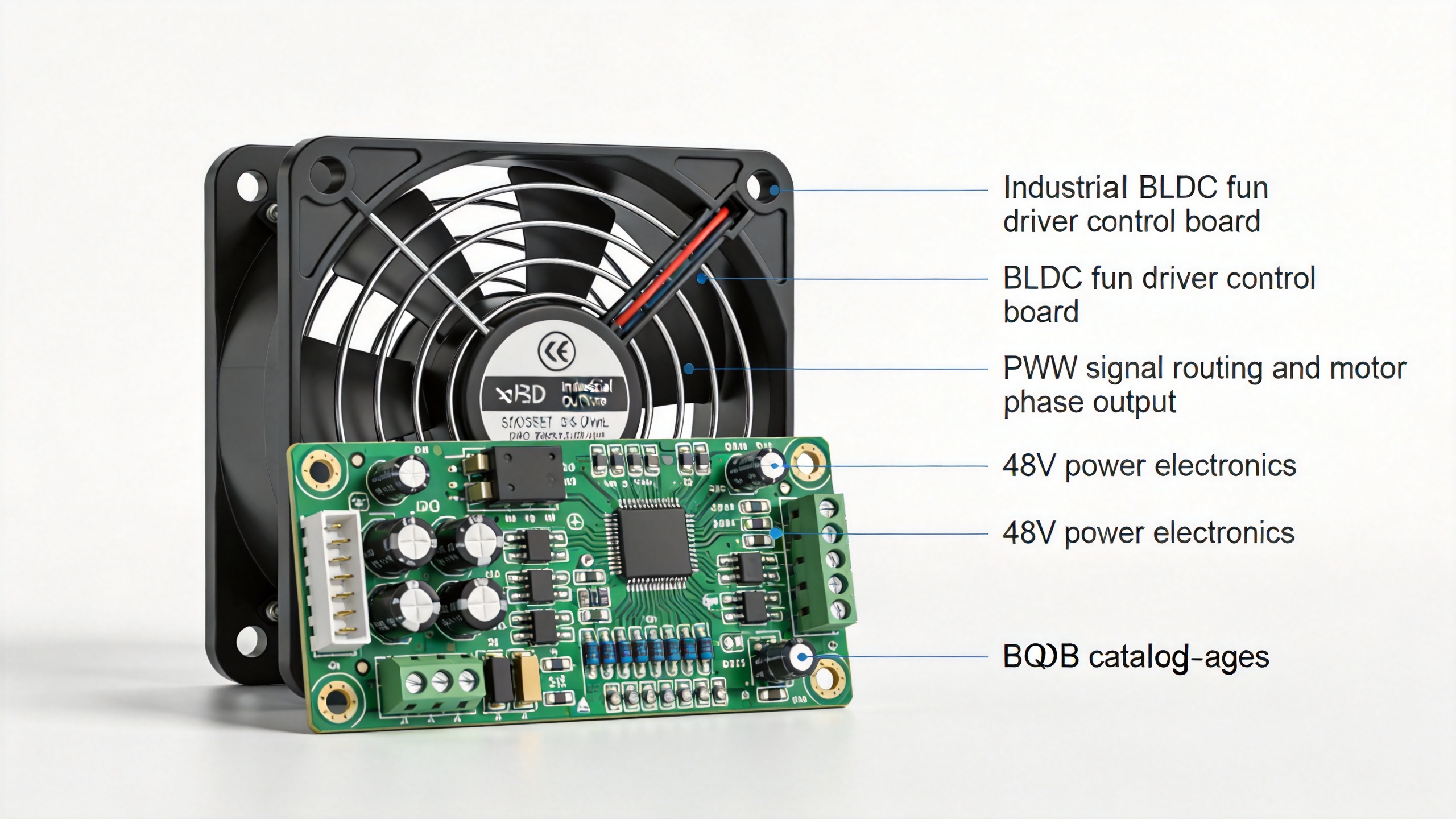
What a Professional BLDC Fan Driver Delivers
When I shifted from evaluating these controllers primarily on input voltage range and current ratings to examining their closed-loop control architecture more carefully, the performance differences in 48V cooling applications became substantially clearer. Datasheet parameters describe steady-state electrical capability. What actually determines behavior under real-world disturbances and load changes.
Closed-Loop Speed Regulation with PWM Precision
PWM speed control is the standard method for this motor type, but its effectiveness depends on the feedback path and loop response time. A professional BLDC fan driver implements true closed-loop control: measured motor speed is continuously compared to the setpoint, and the PWM duty cycle is corrected in real time — unlike open-loop implementations where the duty cycle is static regardless of actual shaft behavior.
For variable speed bldc magnet motor applications that modulate between minimum and full-speed operation based on thermal demand, closed-loop control ensures smooth transitions without hunting. If the load changes unpredictably or motor characteristics drift, the loop needs to be robust enough to maintain stability across those variations rather than simply tracking a fixed setpoint.
Commutation Method and Startup Reliability
Both sensorless and Hall-sensor-based commutation serve 48V cooling fan sets under different conditions. Sensorless control detects back-EMF zero-crossings for phase switching — it eliminates Hall sensor failure as a reliability risk, but requires careful tuning to remain stable at low speeds and during rapid load changes. Hall-sensor commutation provides deterministic timing across the full speed range at the cost of an additional mechanical component in the motor assembly.
For integrators, the key takeaway is: a properly designed controller handles both startup and steady-state commutation as fully specified functions, not edge cases. Generic controllers frequently fail at startup under load because their initialization logic doesn't account for initial rotor position.
Protection Architecture
In 48V cooling applications, driver failure has immediate downstream consequences. Professional implementations include: over-voltage and under-voltage lockout for bus stability, over-current protection calibrated to motor peak current, stall detection with configurable automatic restart, and thermal shutdown of the driver IC itself to prevent cascade failure.
Selection Criteria for 48V Cooling Fan Applications
Lebisen designs its EC and BLDC fan driver products to support both AC and electronically commutated motor fan variants across different project specifications — allowing buyers working on multi-specification cooling systems to consolidate rather than source separate solutions for each voltage range. For 48V brushless DC motor cooling fan sets specifically, the practical evaluation criteria are:
- Input voltage range and ripple tolerance: For telecom applications per ETSI EN 300 132-2, the driver must operate correctly from approximately 36V to 57V DC including transient conditions.
- PWM frequency: Frequencies at 20 kHz and above reduce audible switching noise and improve torque smoothness across the speed range.
- Closed-loop bandwidth: Faster loop response handles rapid speed change requests without overshoot. Match this parameter to the system's expected thermal transient profile.
- Communication interface: PWM input, 0-10V analog, RS-485, or proprietary bus options must align with the thermal management controller's output specification.
Long-Term Stability Across the Motor's Service Life
When selecting components for a cooling fan permanent magnet bldc motor system, motor efficiency curves are an obvious starting point for analysis. What receives less attention is that the driver's ability to adapt to motor parameter changes over operational life matters equally for long-term reliability. Permanent magnet BLDC motors undergo gradual changes in magnetic flux density through repeated thermal cycling. A driver tuned at commissioning may lose optimal commutation timing over time without adaptive algorithms or periodic recalibration capability.
For 48V brushless DC motor cooling fan sets protecting equipment that cannot tolerate unplanned downtime, verify that the selected BLDC fan driver has documented stability performance not just at initial commissioning but across the expected operating temperature range and the motor's full service lifecycle.
Summary
A professional BLDC fan driver stabilizes 48V brushless DC motor cooling fan sets through closed-loop speed regulation with accurate commutation timing, robust protection against bus and thermal disturbances, and adaptive control architecture that maintains performance as motor characteristics evolve over time. For system integrators sourcing cooling fan sets for European, North American, or South American industrial markets, a manufacturer that provides both the fan assembly and the matched driver as a tested combination significantly reduces integration risk compared to separate component sourcing.