EN
EN
What filter matching rule for dust proof cabinet cooling fan operating in cement factories
2026/09/30
Cement cabinets choke on dust. Learn the filter rule for an industrial cabinet cooling fan: G4/F7 media, IP rating, and pre-filter care.

2026/09/20

A variable speed backward curved fan keeps cabinet and process temperatures steady as production demand shifts through the day. By matching airflow to live heat load, it avoids the wasted energy of a fixed-speed unit while protecting sensitive equipment.
Production equipment rarely holds a steady thermal state, and a variable speed backward curved fan earns its value by tracking that moving target. Conveyor ovens, injection molds, welding cells, and compressor racks all shift output with batch size, ambient temperature, and shift schedule. The resulting heat load can swing by a wide margin between a cold morning start and a mid-afternoon peak.
Several factors move the thermal burden hour to hour. Ambient air temperature changes the cooling delta the system must close, while throughput alters frictional and electrical losses inside motors and drives. A mold-release cycle or a curing oven ramp adds scheduled pulses of waste heat. A variable speed backward curved fan must read these swings to size its response, because without measurement the shifts stay invisible until a cabinet trips or a product dimension drifts.
A fixed-speed fan delivers one airflow point on its fan performance curve. To stay safe on the hottest day, specifiers pick a unit sized for peak load. For most operating hours that unit runs well above the actual need, pushing excess airflow against system resistance and burning power it does not use. The inefficiency grows at part load, where a centrifugal fan still draws substantial current even when little cooling is required.
A variable speed backward curved fan solves the mismatch by changing rotational speed to track real-time thermal demand instead of a worst-case assumption. The backward curved impeller holds stable efficiency across a broad speed range, which makes the concept practical rather than merely theoretical.
The control loop starts with measurement. Temperature sensors mounted on the cabinet, duct, or process surface feed a controller that compares the reading to a setpoint. A PID control stage then adjusts the drive output, raising or lowering fan speed to hold the target. Pressure transducers can join the loop to protect against blocked filters or duct restriction. This closed-loop control keeps air delivery matched to the moment, not the calendar. The variable speed backward curved fan therefore runs only as fast as the heat load demands.
Two drive technologies dominate speed regulation. A variable frequency drive (VFD) varies supply frequency to an AC motor, giving smooth soft start and wide turndown. An electronically commutated (EC) motor integrates the inverter and motor into one package with high part-load efficiency and simple 0–10 V or PWM control. Both approaches cut power consumption sharply at partial load because fan power scales roughly with the cube of speed. Selection depends on supply voltage, control architecture, and the existing PLC or BMS.
Backward curved impellers suit variable speed duty because their non-overloading power curve prevents motor overload as speed rises. Air-performance data should be verified to AMCA 210 and ISO 5801, while impeller balance follows ISO 1940 to limit vibration. A variable speed backward curved fan thus stays safe across the whole control range without the resonance issues that plague simpler blade shapes.
A plastics extrusion workshop ran several cooling cabinets along a profile line. Each cabinet held a fixed-speed AC fan sized for summer peak. During winter nights and low-volume shifts the fans ran at full speed regardless of need, and the over-cooling condensed moisture onto control boards. The humidity risk threatened drive failures and nuisance trips when filters clogged, because the fixed airflow could not compensate.
The facility replaced the fixed fans with variable-speed backward curved units driven by EC motors, wired to duct temperature sensors through the line PLC. The closed-loop control held cabinet temperature within a narrow band across seasons. Soft start removed inrush current that had stressed contactors. Energy use dropped by a noticeable margin versus the prior fixed-speed baseline, and condensation on boards stopped. Maintenance staff reported fewer filter-related trips because the controller flagged rising static pressure early. The variable speed backward curved fan units also lowered audible noise in the workspace, supporting a calmer shift environment.
A variable speed backward curved fan turns thermal management from a fixed assumption into a responsive service that follows production equipment as conditions change. The combination of sensor feedback, speed regulation, and a stable backward curved impeller delivers part-load efficiency that fixed units cannot reach.
Specify the duty range, not just peak load: capture minimum and maximum heat load, supply voltage, and IP rating for the environment. Verify CE and UKCA markings on the unit, and request performance data tested to AMCA 210 and ISO 5801 for volume and pressure. Check the motor class against IEC 60034 efficiency rules and confirm balance grade to ISO 1940. Inspect the impeller material, bearing type, and ingress protection against the site's dust and moisture. Request a duty-cycle curve so the selected unit covers both low and high heat-load points.
Commission with the sensor loop live and set a realistic setpoint, not the lowest possible. Follow OSHA 29 CFR 1910.94 ventilation guidance where workers are present, and NFPA 91 for exhaust of vapors and mists. Clean or replace filters on a schedule tied to pressure rise, not the calendar. Log speed and current trends to catch bearing wear early. Keep spare drives matched to the original specification.
What is a variable speed backward curved fan used for?
Answer: This fan type cools cabinets, enclosures, and process equipment whose heat load changes during operation. It pairs a backward curved impeller with a controllable drive so airflow tracks real demand. Common duties include extrusion lines, VFD cabinets, and welding cells. The design holds stable efficiency across a wide speed band, which supports steady thermal management without over-cooling or wasted power.
Why does speed control save energy at part load?
Answer: Fan power scales approximately with the cube of rotational speed, so a small speed reduction yields a large power drop. At part load a fixed fan still draws near full current while delivering unused airflow. A variable speed unit slows down, cutting both airflow and consumption to match the heat load. This avoids the oversizing penalty and reduces operating cost across the many hours spent below peak demand.
How is the sensor feedback loop configured?
Answer: Temperature sensors on the cabinet or process surface feed a controller that compares readings to a setpoint. A PID control stage adjusts the drive output to raise or lower fan speed. Pressure transducers can join to detect filter blockage or duct restriction. The loop holds target temperature by changing speed in real time. Correct setpoint tuning prevents hunting and keeps the system stable through load changes.
Can an EC motor replace a VFD-driven AC fan?
Answer: Yes, an EC motor integrates the inverter and motor in one package and offers high part-load efficiency with simple control signals. It suits retrofit where space and wiring are limited. A VFD with an external AC motor remains valid for large frames or existing AC stock. Both achieve speed regulation; the choice depends on voltage, control architecture, and integration with the site PLC or building management system.
Do these fans need special maintenance routines?
Answer: Maintenance follows a pressure-rise schedule rather than fixed dates. Inspect filters when static pressure climbs, verify bearing noise, and log speed and current trends to detect wear. Balance the impeller to ISO 1940 after any service. Confirm IP sealing and CE or UKCA markings remain intact. Early pressure flags from the controller prevent clog-related trips and protect the thermal balance of the connected production equipment.
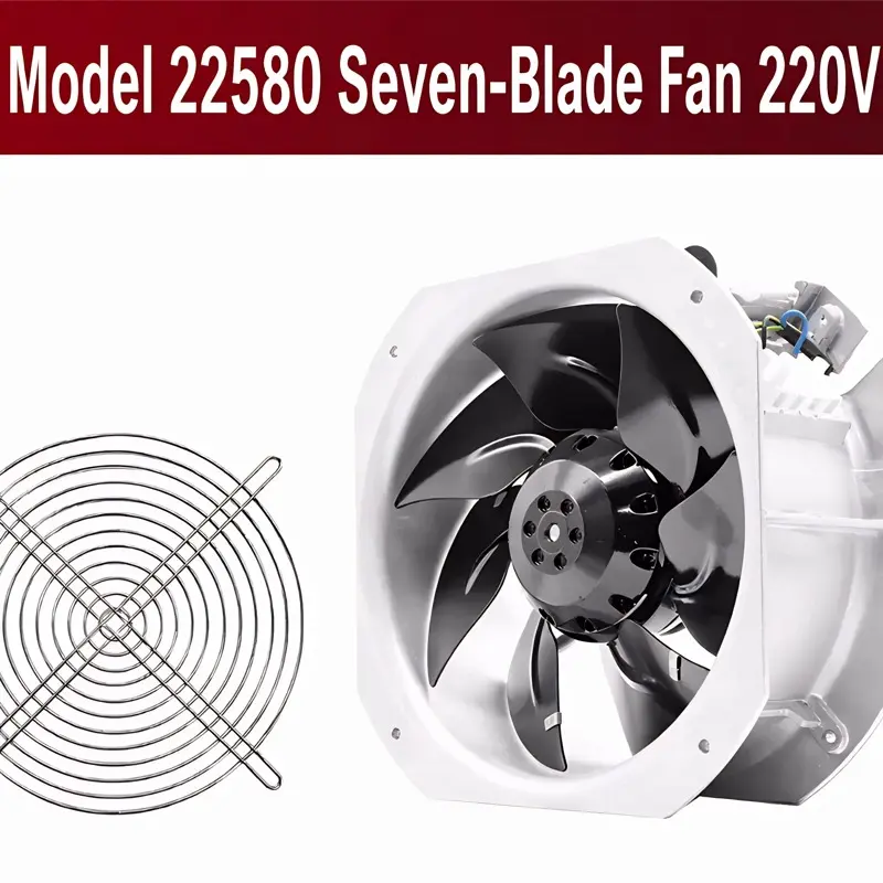
2026/09/30
Cement cabinets choke on dust. Learn the filter rule for an industrial cabinet cooling fan: G4/F7 media, IP rating, and pre-filter care.

2026/10/07
Right wall-mount height for an industrial axial exhaust fan: room volume, free clearance, brackets, and recirculation control.

2026/10/08
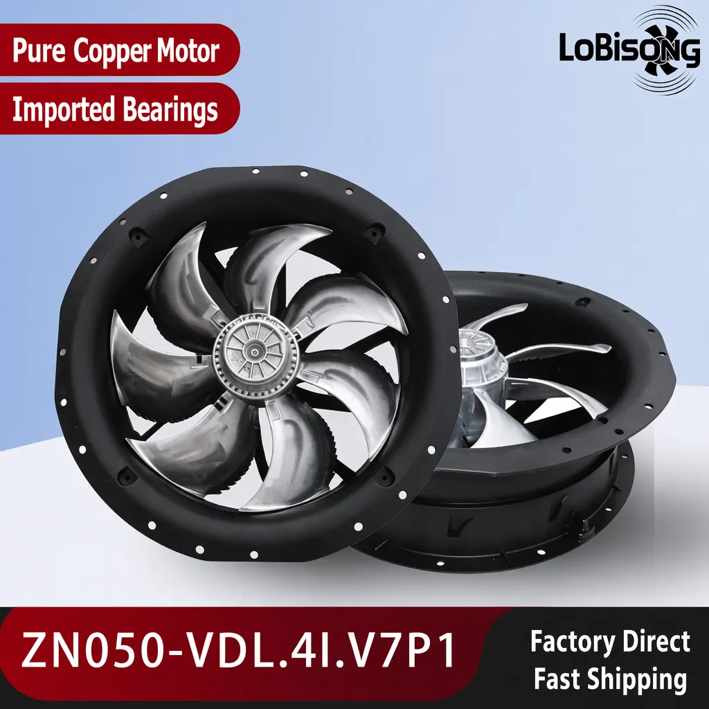
An ec motor fan links to BMS via Modbus, 0-10V and PWM for demand-based cooling, energy scheduling and automatic sensor-driven speed control.
2026/10/06
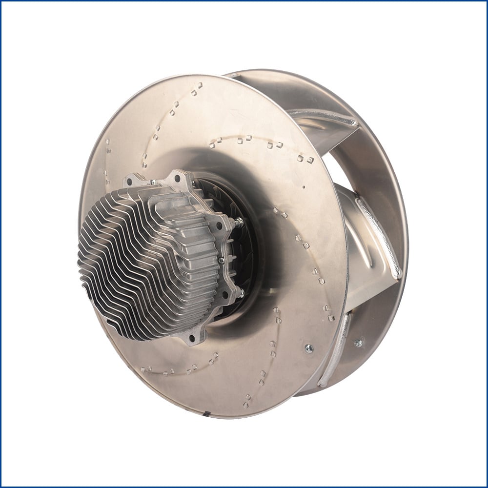
A radial exhaust fan removes grease, fumes, and odors from food-processing workshops with capture velocity and hygienic washdown design.
2026/10/05
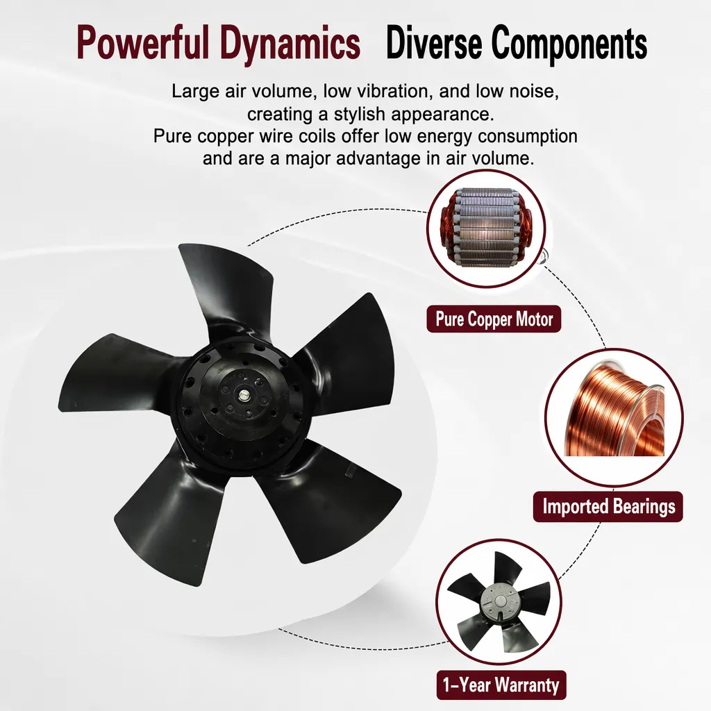
Learn antistatic treatment for industrial cabinet cooling fan in electronics workshops—ESD-safe housing, ionizable plastics, and cleanroom compatibility.
2026/10/04
Discover how a brushless dc servo delivers precise wind speed control for laboratory cooling fans with closed-loop PID feedback and laminar airflow.