EN
EN
What filter matching rule for dust proof cabinet cooling fan operating in cement factories
2026/09/30
Cement cabinets choke on dust. Learn the filter rule for an industrial cabinet cooling fan: G4/F7 media, IP rating, and pre-filter care.

2026/09/22
A server rack ventilation fan does not get selected by guesswork. The airflow it must move is fixed by one number: the heat the rack produces. Every watt of IT load turns into heat that the moving air has to carry away. Undersize the airflow and component temperatures climb until the equipment throttles or shuts down.
The starting point is the nameplate or measured power of everything mounted in the cabinet: switches, compute nodes, storage, and the losses inside power supplies. A half-populated 42U rack can still draw several kilowatts once buffers and redundant supplies are counted. The server rack ventilation fan must move enough air to hold the inlet-to-outlet temperature rise within a safe band, not just cool the primary devices mounted at the front.
One operator retrofitted a 15 kW colocation cabinet that had been running on two generic fans sized from a vendor's "per rack" rule of thumb. Summer ambient pushed inlet temperatures past the comfort zone and the top devices began thermal throttling. After measuring the actual load and applying a heat-balance calculation, the team replaced the original server rack ventilation fan arrangement with higher-CFM axial fans and a controlled pressure margin. Cabinet outlet temperature dropped by roughly 9°C and throttling events stopped. The lesson was simple: calculate from real watts, not from a generic assumption.
The physics is a heat balance. The air carries away power P at a temperature rise ΔT. Density of air ρ and specific heat Cp set how much energy each cubic metre holds, so the same flow cools differently as conditions change.
The core relation is Q = P ÷ (ρ × Cp × ΔT). With air at about 1.2 kg/m³ and Cp near 1005 J/(kg·K), the product ρ × Cp is close to 1206. Rearranged for volume flow, Q in m³/s equals P divided by 1206 × ΔT. The allowed ΔT is the design temperature rise between rack inlet and outlet, commonly 10°C to 15°C for a ventilated cabinet. A smaller ΔT demands more airflow, so the choice of ΔT directly trades fan size against energy use and noise.
Multiplying the m³/s result by 3600 gives m³/h, and by 0.589 gives CFM. A widely used field shortcut is CFM ≈ 3.16 × P(W) ÷ ΔT(°F), which is the same balance expressed in imperial units. For a 15 kW rack with a 15°C (27°F) rise, the requirement works out near 1760 m³/h, or about 1035 CFM. Round up for filter loading and part-load redundancy, then match the fan curve at that operating point rather than at free-air conditions.
A flow number alone is not enough for a server rack ventilation fan specification. The fan must deliver that flow against the resistance the cabinet actually presents, which is rarely zero in a real enclosure.
Cabinet filters, perforated panels, cable trays and bent ducts all add resistance. System impedance rises with the square of flow, so a fan that looks adequate on free-air CFM may collapse once installed. Plot the server rack ventilation fan curve against the cabinet impedance curve; their crossing point is the real operating airflow. Specify a unit that holds the required flow at the expected static pressure, not just at zero load where every fan looks strong.
ASHRAE TC9.9 thermal guidelines place recommended inlet conditions for IT equipment around 18°C to 27°C, which frames the allowable ΔT. ISO 5801 defines how fan performance gets tested, so quoted CFM values stay comparable between suppliers. NFPA 75 covers protection of electronic equipment and influences how cooling and cabling are laid out for fire safety. ANSI electrical standards set the supply tolerances the fan motor must accept. These references turn a back-of-envelope number into a defensible specification.
Sizing is only half the work. The purchased hardware has to stay capable across years of continuous duty, and that depends on choices made before order and habits kept after install.
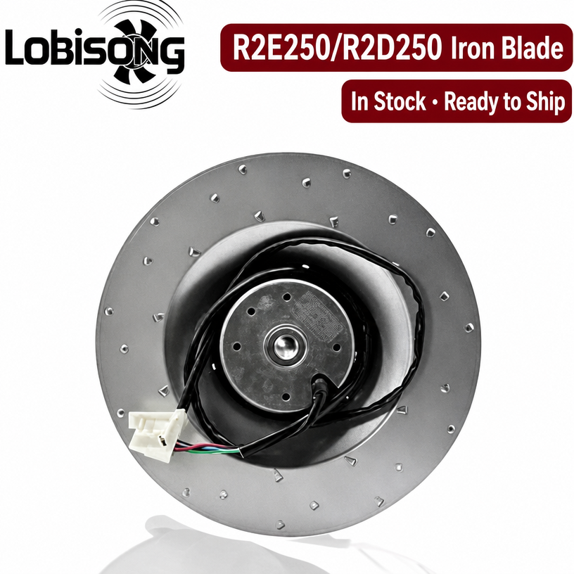
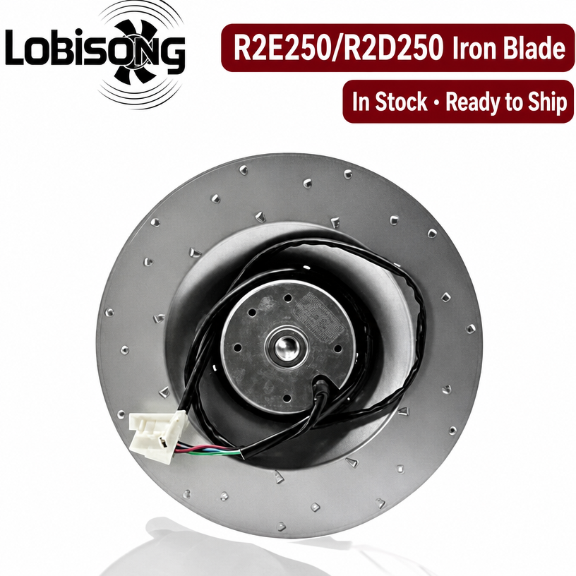
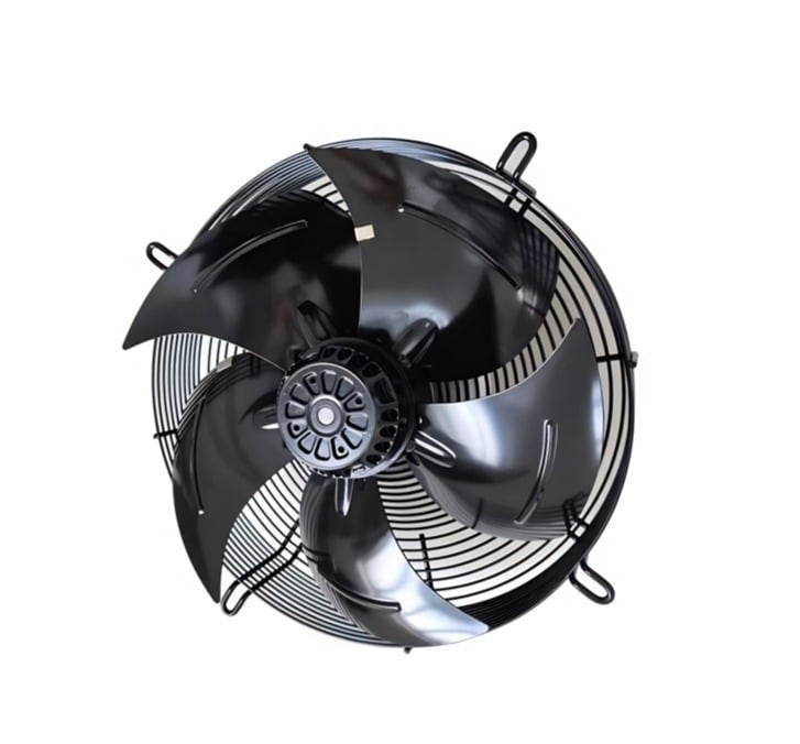
For most ventilated racks, the server rack ventilation fan of choice is an EC axial unit, while centrifugal or filter-fan units suit cabinets with high external resistance. Choose N+1 redundancy so a single failure does not silence all airflow. Match the frame size to the panel cut-out and confirm the rotation direction and airflow path before purchase. Lobisong's EC and AC axial lines, built for cabinet and enclosure cooling, cover the common 115 V to 400 V ranges used in industrial data environments.
Filter screens clog and quietly cut airflow, so schedule visual and differential-pressure checks at regular intervals. Verify that baffles and blanking panels stay in place, because bypass air wastes fan capacity. Listen for bearing noise and watch current draw for drift that signals wear. A short quarterly check keeps the calculated airflow close to the real airflow, which is what actually protects the equipment.
Getting the server rack ventilation fan configuration right starts and ends with the heat balance. Measure real watts, apply Q = P ÷ (ρ × Cp × ΔT), convert to CFM or m³/h, and then validate the result against static pressure and redundancy needs. That disciplined path keeps cabinet temperatures inside the band the equipment expects.
The heat-balance formula is Q = P ÷ (ρ × Cp × ΔT), where P is rack wattage, ρ is air density near 1.2 kg/m³, Cp is about 1005 J/(kg·K), and ΔT is the allowed inlet-to-outlet rise. Convert the result to m³/h by multiplying m³/s by 3600, or use CFM ≈ 3.16 × P(W) ÷ ΔT(°F). Match the fan curve at the required static pressure.
Cabinet filters, panels and ducts create resistance that grows with flow squared. A fan rated on free-air CFM can deliver far less once installed. Plotting the server rack ventilation fan curve against cabinet impedance shows the true operating point. Specifying flow at the expected static pressure prevents silent under-cooling that triggers thermal throttling and shortens hardware life.
Filter screens and baffles should be checked quarterly at minimum, with more frequent checks in dusty or high-load sites. Look for clogging, bearing noise and current drift that signal wear. Keeping blanking panels in place preserves calculated airflow. A short routine inspection protects uptime far better than waiting for a thermal alarm to sound.
ASHRAE TC9.9 sets the recommended IT inlet temperatures that frame the allowed ΔT. ISO 5801 defines comparable fan performance testing, and NFPA 75 addresses protection of electronic equipment, influencing layout and cooling design. ANSI electrical standards cover the supply tolerances fans must accept. Together they make the airflow specification defensible rather than approximate.
A single fan creates a single point of failure and rarely meets both airflow and pressure needs in dense racks. N+1 redundancy keeps cooling alive if one unit fails. EC axial fans suit most ventilated cabinets, while centrifugal units fit high-resistance enclosures. Size from measured watts, then confirm the configuration against real operating conditions before commissioning.
2026/09/30
Cement cabinets choke on dust. Learn the filter rule for an industrial cabinet cooling fan: G4/F7 media, IP rating, and pre-filter care.

2026/10/07
Right wall-mount height for an industrial axial exhaust fan: room volume, free clearance, brackets, and recirculation control.

2026/10/08
An ec motor fan links to BMS via Modbus, 0-10V and PWM for demand-based cooling, energy scheduling and automatic sensor-driven speed control.
2026/10/06
A radial exhaust fan removes grease, fumes, and odors from food-processing workshops with capture velocity and hygienic washdown design.
2026/10/05
Learn antistatic treatment for industrial cabinet cooling fan in electronics workshops—ESD-safe housing, ionizable plastics, and cleanroom compatibility.
2026/10/04
Discover how a brushless dc servo delivers precise wind speed control for laboratory cooling fans with closed-loop PID feedback and laminar airflow.