EN
EN
What filter matching rule for dust proof cabinet cooling fan operating in cement factories
2026/09/30
Cement cabinets choke on dust. Learn the filter rule for an industrial cabinet cooling fan: G4/F7 media, IP rating, and pre-filter care.

2026/09/04
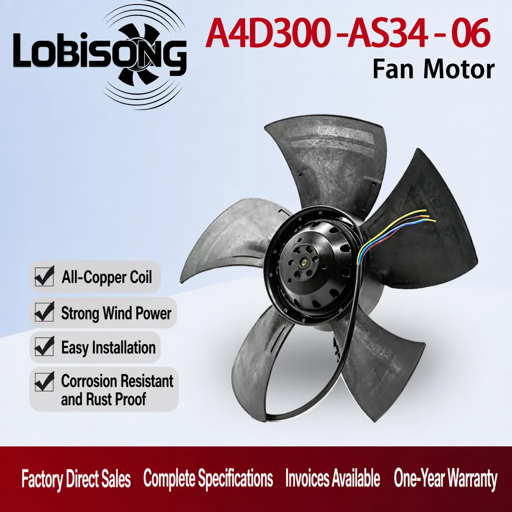
New-generation ec fans and drives combine an electronically commutated motor with a built-in controller, turning a cooling device into a networked sensor node. For buyers serving Europe, Russia, India, and the Americas, this shift matters because enclosure and VFD cabinet reliability now depends on real-time data, not just airflow. The following sections explain what monitoring is built in, why it works, and how to deploy it with confidence.
A modern ec fans and drives package places the drive electronics directly on the fan. The EC motor uses a brushless outer rotor design where the controller switches stator phases through precise commutation. Instead of an external variable frequency drive, the drive reads rotor position and regulates current. This integration is what makes continuous monitoring possible: the same circuit that spins the impeller also measures voltage, current, and operating state every cycle. Pure-copper windings and precision ball bearings keep heat generation low for stable long-term readings.
Inside the motor, a hall sensor tracks magnetic field position and returns a speed feedback signal. That signal lets the controller hold a target rpm and lets a host PLC confirm the fan is running. When PWM input adjusts the setpoint, the EC motor responds with closed-loop accuracy. If the measured speed drifts below the commanded value, the system flags a stall or blocked-impeller condition before temperatures climb. Such feedback turns a passive cooler into a self-reporting component. For buyers evaluating ec fans and drives, the locked-rotor and stall flags simplify remote troubleshooting: a technician confirms fan health from the PLC without opening the enclosure, and the rpm trace gives a clear fault record for commissioning teams.
For cabinet networks, ec fans and drives expose monitoring through Modbus over RS485. A single bus polls several fans for rpm, current, temperature, and alarm status without extra wiring. This serial link keeps installation simple while delivering the data a building management system needs. CE, IEC, and EN compliance means the communication layer meets the electrical and EMC expectations of European buyers. With a consistent protocol, maintenance teams read every fan from one screen.
Thermal protection sits at the core of safe operation. The controller watches winding temperature and input current; when either exceeds the limit, it triggers a thermal overload trip and raises an alarm output. An overcurrent or locked-rotor event is caught in milliseconds, cutting power before insulation fails. In one steel-plant case, a legacy fixed-speed fan ran until dust blocked the impeller and a drive fault stopped the line. With monitoring, the same blockage trips an alarm within seconds so staff clear the filter before production halts. The alarm contact can drive a central warning or a safe shutdown sequence.
The control logic in these EC fans uses ambient and motor temperature sensing to vary speed. On a cool morning the fan slows; during peak load it ramps to full rpm. Variable speed control matches airflow to the actual heat load, which lifts efficiency and trims energy consumption. The same sensor data feeds the host system, so operators see thermal trends rather than a single on/off state. That visibility supports smarter enclosure ventilation planning and steadier component temperatures across the year.
For these integrated fans, continuous monitoring produces the trend data that predictive maintenance depends on. A slow rise in current draw or a falling rpm at a fixed PWM setpoint often precedes bearing wear. Catching that drift early lets a plant schedule a swap during planned downtime instead of reacting to a failure. Combined with the IP54 ingress protection and sealed bearing design, the alerting helps extend service life. Maintenance becomes a scheduled task rather than an emergency. Beyond bearings, a steady airflow drop at constant rpm can signal a clogged filter or an aging drive curve. One food plant used these logs to swap a worn unit during a planned stop, avoiding a peak-hour breakdown.
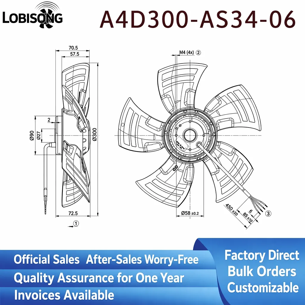
Specifying ec fans and drives starts with the heat load, not the catalogue number. Match the fan's airflow and static pressure to the cabinet's dissipation need, then let the variable frequency drive logic hold the minimum speed that keeps components in range. Because the EC motor avoids external VFD losses and runs only as fast as required, energy savings accumulate across thousands of operating hours. Ask for CAD drawings and IEC, EN test data before release, and confirm the register map matches the PLC.
After installation, verify alarm wiring and confirm Modbus registers return live values. Check the impeller for dust every quarter and confirm rpm tracks the PWM command. Inspect the gasket and enclosure seal so ingress protection holds, and review logged current trends for a gradual climb. These steps turn the built-in monitoring into a working safeguard rather than an unused feature. A short commissioning checklist prevents most field surprises and protects enclosed equipment from silent overheating. Buyers standardizing on ec fans and drives across several enclosures gain one spare-part type and one monitoring screen, which lowers long-term support cost and simplifies acceptance testing.
Choosing ec fans and drives with integrated monitoring changes how a buyer manages enclosure cooling. Speed feedback, alarms, and Modbus visibility let teams spot risk early, while built-in thermal protection and variable speed control cut energy use and protect the motor. For global B2B projects, the combination of CE, IEC, and EN compliance with self-reporting intelligence makes these fans a practical foundation for reliable VFD cabinet cooling.
What intelligent monitoring functions come built into new-generation EC fans? New ec fans and drives embed a controller that reports speed, current, temperature, and alarm state. A hall sensor feeds speed feedback, while Modbus over RS485 carries the data to a PLC. Thermal protection trips on overload and signals the host. This lets operators confirm cooling is active and detect stalls before heat builds, turning a fan into a monitored node.
Why does an EC motor need a built-in drive for monitoring? The drive sits on the fan and reads rotor position through commutation, so it already measures current and voltage each cycle. That same circuit reports operating state without extra sensors. An external VFD cannot see inside the motor as directly. Built-in electronics therefore give closed-loop control and the data bus needed for predictive maintenance in one compact package.
How does thermal protection prevent cabinet damage? The controller watches winding temperature and input current continuously. On overcurrent or locked rotor it opens a thermal overload trip and raises an alarm within milliseconds. Power cuts before insulation degrades. In dusty or hot sites this stops silent overheating. The alarm contact can trigger a central warning or safe shutdown, protecting both the fan and the enclosed equipment.
Can Modbus communication work without a separate VFD? Yes. These fans carry their own controller, so Modbus over RS485 links directly to the building management system. No external variable frequency drive is required for speed or monitoring. A single bus polls multiple fans for rpm, current, and alarm status. CE, IEC, and EN compliance keep the link within expected EMC and safety limits for European sites.
Where should buyers verify monitoring before purchase? Request the IEC and EN test reports plus CAD drawings, then confirm the alarm output and Modbus register map during commissioning. Check that rpm tracks the PWM command and that the host reads live temperature and current. Inspect the enclosure seal and IP54 rating so ingress protection holds. A short checklist ensures the monitoring actually works in the field.
2026/09/30
Cement cabinets choke on dust. Learn the filter rule for an industrial cabinet cooling fan: G4/F7 media, IP rating, and pre-filter care.

2026/10/07
Right wall-mount height for an industrial axial exhaust fan: room volume, free clearance, brackets, and recirculation control.

2026/10/08
An ec motor fan links to BMS via Modbus, 0-10V and PWM for demand-based cooling, energy scheduling and automatic sensor-driven speed control.
2026/10/06
A radial exhaust fan removes grease, fumes, and odors from food-processing workshops with capture velocity and hygienic washdown design.
2026/10/05
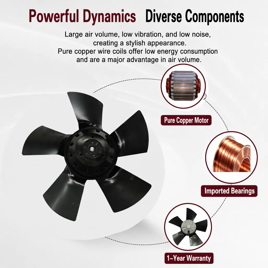
Learn antistatic treatment for industrial cabinet cooling fan in electronics workshops—ESD-safe housing, ionizable plastics, and cleanroom compatibility.
2026/10/04
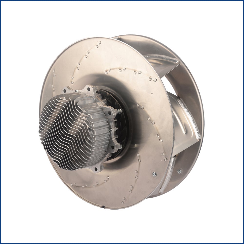
Discover how a brushless dc servo delivers precise wind speed control for laboratory cooling fans with closed-loop PID feedback and laminar airflow.