EN
EN
What filter matching rule for dust proof cabinet cooling fan operating in cement factories
2026/09/30
Cement cabinets choke on dust. Learn the filter rule for an industrial cabinet cooling fan: G4/F7 media, IP rating, and pre-filter care.

2026/09/05

A reliable power-consumption test for a DC-motor-equipped cabinet cooling fan starts long before any meter is connected. The fan's energy draw shifts with every operating point, so the test must exercise the full dc motor speed control range rather than a single rated condition. A buyer who skips this step sees only one static number and misses how the fan truly behaves under partial load. That gap turns a specification into a guess, which is unacceptable for enclosure thermal design.
Industrial enclosure cooling carries a hidden cost that appears only when the fan actually runs. Documenting that cost requires disciplined measurement and a clear method before samples arrive on the dock.
A European panel builder recently sourced 400 cabinet cooling fans and needed proof of the supplier's energy claim. The quoted figure looked attractive, but the procurement team required an independent check before release. They built a small rig, connected a power analyzer, and ran the dc motor speed control through its full duty-cycle span to record actual watts at each step. The measured results differed from the datasheet by up to 18 percent at low speed.
The independent test protected the buyer from specifying a fan that would overrun the cabinet's cooling budget. After renegotiating the quoted model and confirming a second sample, the installation met its thermal envelope with margin. The episode shows why power testing belongs in supplier qualification, not just final incoming inspection.
An under-stated power rating hides the true load on the cabinet's DC supply and risks tripping protection during summer peaks. An over-stated rating pushes buyers toward a larger, costlier fan than the enclosure needs, distorting total cost of ownership and complicating CE and IEC compliance paperwork. Worse, running a cabinet cooling fan at the wrong point in its dc motor speed control band can raise internal temperature instead of lowering it. If airflow drops below demand, the motor draws more current and a thermal feedback loop forms; a speed sweep exposes the danger zone.
The link between control signal and energy use is physical, not arbitrary. Understanding it is the difference between a meaningful test and a cosmetic one.
Pulse-width modulation drives the brushless outer-rotor motor by switching the supply on and off at high frequency. The duty cycle—the share of each cycle the voltage stays high—sets the average applied voltage and therefore the RPM. Because mechanical output scales with the cube of speed, even a small duty-cycle change moves power consumption sharply. This dc motor speed control logic explains why a power test must pin down the duty cycle at every measurement point rather than assume a linear trend.
Beyond PWM, some controllers vary the DC bus voltage directly; this dc motor speed control path also changes power in a predictable but non-linear way. Lower voltage reduces both RPM and input power, though the relationship flattens near the motor's starting threshold. A thorough test records both methods, because a cabinet may mix PWM drives and analog voltage regulators across its service life. CE and IEC references guide the safe voltage limits for the winding insulation class.
A power analyzer measures true RMS voltage, current and instantaneous power, then integrates to watts and watt-hours. For a DC fan the readings are steady, but ripple from the drive still matters, so a device with high sampling rate captures real input power. Paired with a tachometer for RPM, the analyzer turns raw numbers into an efficiency curve the engineering team can trust. Skipping the analyzer in favor of a simple multimeter leaves switching losses invisible.
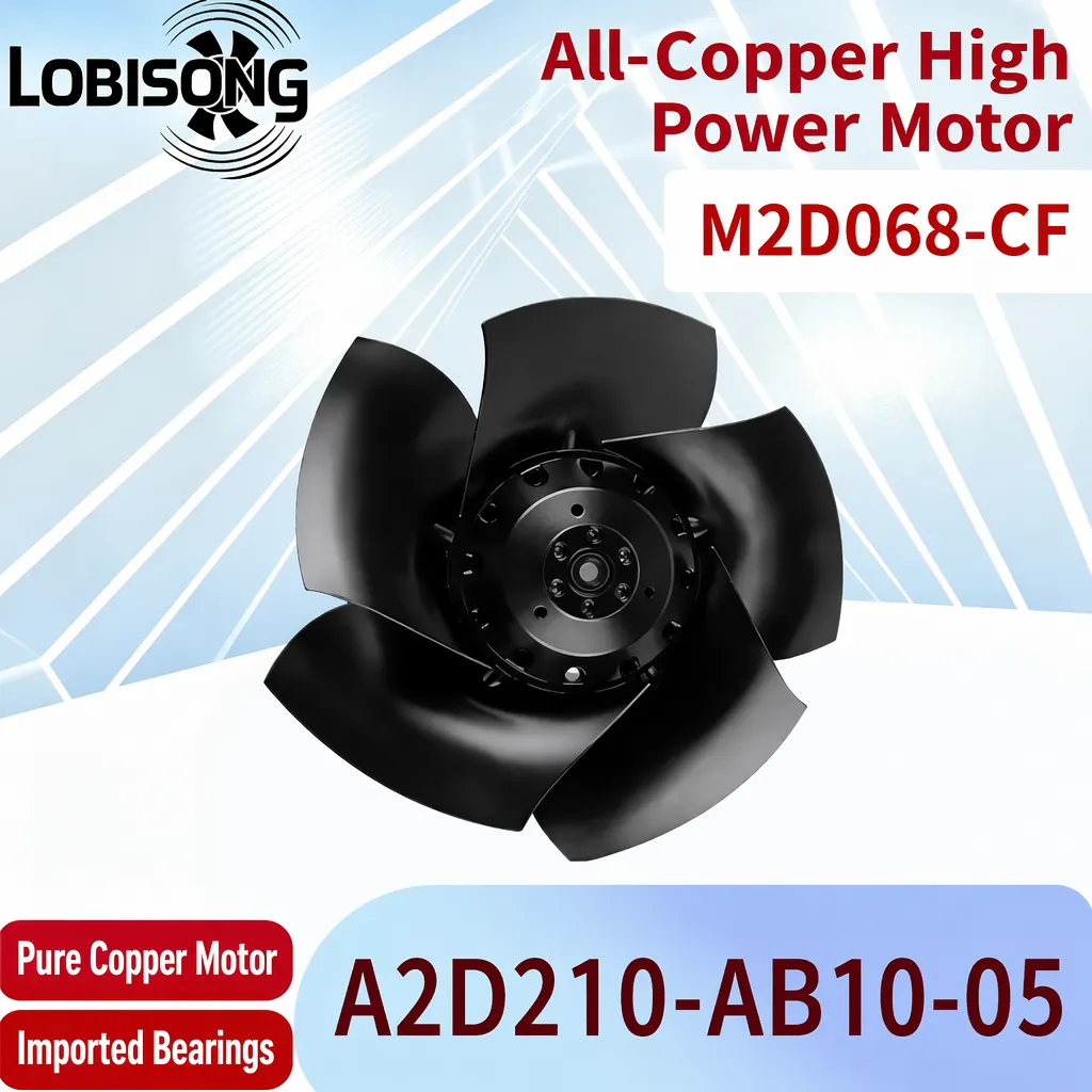
A repeatable procedure keeps results comparable between suppliers and between batches. The sequence below works for most DC-motor-equipped cabinet cooling fans.
Mount the cabinet cooling fan in a representative enclosure or wind tunnel to reflect real back-pressure. Connect a calibrated power analyzer in series with the DC supply, add a tachometer, and log ambient temperature. Use pure-copper-winding samples where possible, since winding quality changes heat generation and therefore power. Record rated voltage and the controller's dc motor speed control mode—PWM or analog voltage—before starting, and note the IP rating of the test sample.
Begin at minimum speed and raise the setpoint in even steps across the dc motor speed control range—for example ten increments of PWM duty cycle from 10 to 100 percent. At each step, let the fan stabilize, then capture voltage, current and watts. Plotting power against duty cycle reveals whether the fan tracks the expected cubic law and where losses concentrate. Repeat the sweep in both directions to catch hysteresis in the bearings.
Convert the logged data into an efficiency curve by relating input watts to delivered airflow or static pressure. The curve shows the sweet spot where the cabinet cooling fan moves the most air per watt. Sharing this curve with the supplier supports a fact-based purchase decision and simplifies later maintenance planning, because normal wear shifts the curve in a predictable way that technicians can track over the fan's service life.
Specifying a DC-motor-equipped cabinet cooling fan without a documented power test leaves energy budgets exposed to datasheet error. The sound approach exercises the dc motor speed control range with a calibrated power analyzer, records voltage, current and watts at every setpoint, and turns the data into an efficiency curve. Buyers who test before purchase gain a defensible number, avoid thermal risk, and select a fan that truly fits the enclosure for the long term.
A calibrated power analyzer, a stable DC supply, a tachometer and a representative enclosure make up the basic rig. The analyzer records voltage, current and true watts, while the tachometer confirms RPM against the controller setting. Logging ambient temperature keeps the result comparable. For PWM drives, choose an analyzer with fast sampling to capture switching ripple. CE- and IEC-aligned setups also document the insulation class limits before testing begins.
Fan power follows a near-cubic law versus speed, so small changes in RPM move watts sharply. The dc motor speed control method—whether PWM duty cycle or DC voltage—sets that speed, and the motor then draws the current needed to sustain it. Measuring only at full speed hides the low-end losses that matter most in variable-load cabinets. A full sweep across the control range exposes the true consumption profile.
A sweep of eight to twelve evenly spaced steps across the control range captures the shape without wasting time. Fewer steps miss the knee where efficiency drops; more steps add little beyond noise. Record voltage, current and watts at each stable point, let the fan settle, and repeat any reading that drifts. The resulting efficiency curve supports confident purchasing and maintenance planning.
Yes. If the cabinet cooling fan runs below the airflow the heat load demands, internal temperature climbs and the motor draws more current, creating a thermal loop. Testing across the speed band shows the safe operating window and the point where cooling fails. Specifying the correct setpoint during commissioning, and verifying it on site, prevents thermal trip and protects the enclosure's components over time.
The curve belongs in the procurement file, the commissioning checklist and the maintenance manual. Procurement uses it to compare models on watts per airflow, commissioning sets the correct speed, and maintenance tracks drift against the original baseline. Suppliers such as Lobisong can provide CAD drawings and test support, so the documented curve stays relevant through the fan's service life in the field.
2026/09/30
Cement cabinets choke on dust. Learn the filter rule for an industrial cabinet cooling fan: G4/F7 media, IP rating, and pre-filter care.

2026/10/07
Right wall-mount height for an industrial axial exhaust fan: room volume, free clearance, brackets, and recirculation control.

2026/10/08
An ec motor fan links to BMS via Modbus, 0-10V and PWM for demand-based cooling, energy scheduling and automatic sensor-driven speed control.
2026/10/06
A radial exhaust fan removes grease, fumes, and odors from food-processing workshops with capture velocity and hygienic washdown design.
2026/10/05
Learn antistatic treatment for industrial cabinet cooling fan in electronics workshops—ESD-safe housing, ionizable plastics, and cleanroom compatibility.
2026/10/04
Discover how a brushless dc servo delivers precise wind speed control for laboratory cooling fans with closed-loop PID feedback and laminar airflow.