 EN
EN
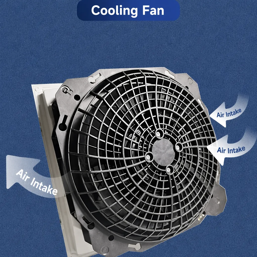
What Remote Monitoring System Matching Scheme for Industrial Cooling Fan Units
When I first worked on integrating monitoring into an industrial cooling installation, my team spent more time debugging control interface mismatches than commissioning the fans. The fans were running fine — it was the signal wiring, protocol settings, and feedback loops that kept causing problems. That experience shaped how I now think about remote monitoring for ec fans and drives: the monitoring scheme must be matched to the specific demands of the installation from the start, not bolted on later.
Industrial cooling fan units — whether installed in electrical cabinets, HVAC air handling equipment, or process ventilation systems — are increasingly expected to do more than move air. Facility managers want real-time status, early fault detection, and automated responses to changing conditions. The real question is which monitoring scheme actually fits your ec fans and drives setup.
Why Industrial Cooling Fan Units Need Remote Monitoring
Industrial fan units in continuous operation are rarely in easy-access locations. Electrical cabinet fans, rooftop HVAC units, and inline duct fans may run around the clock in environments where manual inspection is infrequent. When these units fail without warning, the consequences range from overheated control panels to full production stoppages.
One recurring observation in the field: facilities that plan fan replacement cycles based solely on rated bearing lifespan often experience unexpected early failures. High ambient temperatures, elevated dust loads, or higher-than-expected operational hours can all shorten actual service life compared to standard datasheet ratings. Remote monitoring — even basic speed and alarm signal monitoring — provides early warning that manual inspection schedules cannot.
The industry shift toward EC motor technology has made this far more practical. Unlike traditional AC fan units, which offer limited real-time feedback, ec fans and drives are built with integrated electronics that generate digital data: speed feedback, power consumption, alarm outputs, and communication bus interfaces. The monitoring capability is already in the product. What changes is how you connect it to your industrial ventilation system maintenance workflow.
What Makes EC Fans and Drives Suited for Remote Monitoring
EC fans operate on electronically commutated motor technology — brushless permanent magnet motors with onboard control electronics. This architecture means the fan unit is already processing digital information during operation: actual rotor speed, motor temperature status, operating hours, and fault conditions. EC fans and drives with built-in speed feedback can maintain closed-loop control output, meaning the drive adjusts to hold a target speed even as duct resistance changes over time.
For remote monitoring purposes, that creates a real and accessible data source — provided the monitoring system interface matches what the fan drive actually outputs. EC fans and drives typically support one or more of three signal types: analog voltage (0-10V), digital pulse-width modulation (PWM), or serial communication via Modbus RS485. The right match depends on what data you need and how many units you are monitoring.
One thing you notice when comparing EC fans and AC fans side-by-side in a monitored installation is how differently they behave under variable load. EC fans hold their target speed steadily with minimal hunting; the speed feedback is stable and predictable, which simplifies threshold-based alarm logic in the monitoring system.
Three Core Monitoring Interface Options for EC Fan Systems
0-10V Analog for Simple Speed Demand and Basic Feedback
The 0-10V analog interface is the most widely supported control input across EC fan models. It provides a one-way speed demand signal — the controller sends a voltage corresponding to the desired fan speed, and the fan responds. Some EC fans and drives also provide a 0-10V feedback output representing actual speed, allowing a basic monitoring loop without requiring a digital communication protocol.
This interface suits installations where monitoring is limited to confirming the fan runs at a set point. It works well in straightforward single-zone systems where the control interface is already analog. The limitation is that it carries no alarm or diagnostic data — fault conditions are not communicated through the analog signal alone.
PWM for OEM and Controller-Integrated Installations
Pulse-width modulation (PWM) is the preferred interface when the fan is integrated into an OEM equipment board or a dedicated fan controller that natively outputs PWM signals. PWM is a digital signal that adjusts fan speed by varying pulse width, offering precise speed demand with fast response times.
Like 0-10V, PWM is typically a one-way control signal in standard ec fans and drives applications. It does not inherently carry status or fault data back to the monitoring system. Buyers integrating EC fans into custom equipment should verify the PWM frequency and voltage level specification against the fan drive input requirements before committing to a design, as mismatches here are a common integration problem.
Modbus RS485 for Multi-Fan Monitoring and BMS Integration
When industrial ventilation system maintenance requirements include reading fan status, current speed, power consumption, alarm codes, or operating hours — or when multiple fan units need to be monitored from a central BMS or SCADA system — Modbus RS485 is the recommended interface. It is the only standard interface among the three that provides two-way digital communication between the fan drive and the monitoring system.
With Modbus, each fan unit is assigned a unique address, allowing a single RS485 bus to carry data from multiple units back to one monitoring controller. The BMS or monitoring platform can read registers for each fan individually: actual speed, output power, fault codes, and accumulated operating hours. This creates the data foundation for condition-based maintenance scheduling — replacing guesswork with actual operating data from your ec fans and drives.
EC motors can be integrated with Building Management Systems and IoT platforms in this way, enabling remote monitoring, automation, and performance tracking that was not practical with AC fan technology. For facilities with more than three or four monitored fan units, Modbus RS485 usually delivers better return on integration effort than parallel analog wiring.
How to Match Your Monitoring Scheme to Your Application
The right monitoring scheme depends on answering a few focused questions before specifying the interface:
- How many fan units need to be monitored? Single units with simple status needs may work with analog. Multi-unit installations with central monitoring should default to Modbus RS485.
- What data do you actually need? Speed setpoint confirmation only — 0-10V or PWM. Speed, power, faults, and alarms — Modbus RS485.
- Is there an existing BMS or SCADA system? Confirm which protocols it supports before selecting the fan drive variant. EC fan drive models often come in analog-only and Modbus-capable variants — this choice cannot easily be changed after installation.
- What are the ambient conditions? High-temperature environments shorten component service life more than published MTBF figures suggest. Automated status checks via Modbus reduce the risk of undetected degradation between manual inspections.
Matching ec fans and drives to a monitoring scheme is less about selecting the most sophisticated option and more about selecting the option that fits within the actual operational infrastructure. A Modbus-capable fan drive installed in a facility with no RS485 infrastructure delivers no monitoring value — while the same drive correctly wired into a BMS can cut maintenance costs through early fault detection.
Practical Considerations for Industrial Ventilation System Maintenance
Remote monitoring does not eliminate the need for periodic industrial ventilation system maintenance — it makes maintenance more targeted. Facilities using EC fan monitoring data can schedule bearing inspections based on actual operating hours rather than calendar intervals, and can identify units running above thermal thresholds before thermal protection activations cause unplanned downtime.
For trading companies and panel builders sourcing EC fan and drive packages, the monitoring interface selection should be discussed at the specification stage. Downstream customers who later discover their installed fans lack Modbus capability — when their facility management team expects BMS integration — face a costly retrofit. Specifying matched fan and drive combinations from a supplier who supports both the fan unit and the drive electronics simplifies integration and reduces post-installation compatibility risk.
Lebisen's EC axial fan and drive systems are designed for integration into variable-speed HVAC and building automation applications, with support for standard analog and digital control interfaces. For buyers evaluating monitoring-ready ec fans and drives solutions for industrial or commercial cooling applications, the matched fan-drive portfolio approach reduces the specification risk that comes from sourcing motor and driver from separate suppliers. Contact Lebisen to discuss monitoring-compatible EC fan configurations for your application.