EN
EN
What filter matching rule for dust proof cabinet cooling fan operating in cement factories
2026/09/30
Cement cabinets choke on dust. Learn the filter rule for an industrial cabinet cooling fan: G4/F7 media, IP rating, and pre-filter care.

2026/08/29

Server room thermal failures follow a predictable pattern. Hardware density expands, thermal loads outpace existing HVAC infrastructure, hot spots form above the upper rack enclosures, and thermal throttles or system shutdowns occur. Resolving these localized heat issues requires accurate fluid dynamics calculations rather than guesswork.
Applying a precise temperature difference formula establishes the exact volumetric airflow required to maintain steady operating temperatures. Calculating required airflow based on heat output and targeted delta T ensures that server room cooling fan specifications are backed by thermodynamic principles.
Sensible heat transfer by moving air is governed by the core thermodynamic equation:
Q = m * cp * Delta T
Where Q represents total heat generation in kilowatts, m is the mass flow rate of air, cp is the specific heat capacity of air (approx 1.005 kJ/kg·K), and Delta T is the temperature differential between rack intake and exhaust streams.
Converted to volumetric flow rate for practical engineering applications, the standard server room airflow calculation formula is:
V = (3.0 * Q) / Delta T
V: Required airflow rate (m3/h)
Q: Total IT equipment heat load (kW)
Delta T: Targeted temperature differential (K or °C)
In imperial units, this converts to CFM = (3.16 * Q_watts) / Delta T_F.
This mathematical relationship highlights a critical engineering reality: reducing the allowable temperature difference across the room by half doubles the air volume that a high airflow server room cooling fan array must deliver.
Selecting the target temperature difference bridges theoretical calculations with real-world hardware operational limits. ASHRAE Thermal Guidelines for Data Processing Environments recommend server inlet temperatures between 18°C and 27°C.
10 K to 12 K Delta T (Standard Design Point): Maintains return air temperatures around 37°C while preserving safety margins for future equipment expansion.
14 K to 16 K Delta T (High-Density / Legacy Gear): Allows fewer cooling units and lower overall fan power consumption, but increases hot aisle ambient temperatures.
8 K to 9 K Delta T (Precision Environment): Keeps hardware cooler and extends component lifespans, but requires significantly higher airflow capacity.
When performing cabinet cooling fan sizing, calculate both room-level airflow totals and localized rack-level target flows for high-density blade enclosures to ensure adequate capture velocity across all server inlets.
| Target Delta T (Delta T) | Airflow Required (10 kW Load) | Airflow Required (10 kW Load) | Relative Fan Unit Count | Operational Impact |
| 8 K | 3,800 m3/h | 2,240 CFM | 2 Units + Redundancy | Maximum cooling margin; higher fan power draw |
| 10 K | 3,040 m3/h | 1,790 CFM | 2 Standard Units | Optimal design balance for standard server racks |
| 12 K | 2,530 m3/h | 1,490 CFM | 1 Large Unit + Standby | Lower initial fan cost; warmer hot aisles |
| 15 K | 2,030 m3/h | 1,195 CFM | 1 High-Capacity Unit | Check maximum server rear exhaust tolerances |
| 20 K | 1,520 m3/h | 895 CFM | 1 Low-Speed Unit | Spot cooling only; unsuitable for dense server arrays |
A common oversight during cabinet cooling fan sizing is evaluating fans solely by their free-flow catalog ratings (0 Pa static pressure).
In real-world server rooms, air encounters airflow resistance from multiple internal components:
High-Density Air Filters: 30 Pa to 70 Pa pressure drop
Perforated Mesh Doors & Baffles: 20 Pa to 50 Pa pressure drop
Internal Cable Bundles & Cable Trays: 15 Pa to 40 Pa pressure drop
Exhaust Louvers & Dampers: 10 Pa to 30 Pa pressure drop
Total system static resistance typically ranges between 75 Pa and 180 Pa. A server room cooling fan specified without accounting for these resistive pressure drops will deliver substantially less airflow than its nameplate rating once installed inside a cabinet or wall assembly. Always verify the fan curve at operating static pressure points.
A logistics distribution center experienced recurring over-temperature alarms in its central server facility following a network equipment expansion.
Initial State: The equipment room housed a 9 kW total IT load served by legacy exhaust fans. Server inlet temperatures reached 31°C on summer afternoons due to air recirculation and inadequate static pressure capacity.
Calculated Solution: Applying the standard server room airflow calculation with a target 10 K Delta T indicated a required total airflow of approximately 2,700 m3/h.
Hardware Upgrades: The facility installed dual high airflow server room cooling fan units rated at 2,800 m3/h at 120 Pa static pressure in an N+1 arrangement, sealed cable pass-throughs, and added blanking panels to prevent hot air bypass.
Results: Average rack intake temperatures dropped to a stable 24°C, hot spots were eliminated, and the cooling layout established sufficient capacity to support an additional 3 kW of rack expansion.
Building high-availability server ventilation requires incorporating structural redundancy and dynamic motor control into the design:
N+1 Redundant Arrays: Installing an extra cooling fan ensures continuous airflow in the event of a motor failure or during routine maintenance.
Variable Speed Control (EC/PWM): Equipping fan assemblies with speed-controllable motors allows airflow to scale automatically based on real-time temperature sensors. According to fan affinity laws, reducing fan speed to 80% cuts power consumption by nearly 50%.
Physical Containment: Seal floor grommets, install blanking panels in unused rack units, and isolate hot/cold aisles to prevent supply air bypass before adding extra fan units.
Implementing reliable server room ventilation systems demands high-performance equipment verified against strict static pressure standards.
LOBISONG manufactures industrial cooling fans, equipment ventilation units, and specialized cabinet blowers across seven automated production lines. Operating under certified ISO, CE, and UKCA standards, product lines deliver full technical parameters, CAD dimensional integration files, and verified static pressure performance curves for critical infrastructure supply chains worldwide.
Matching fan selection to calculated heat loads, target Delta T parameters, and true system static pressure delivers continuous thermal protection, optimized energy efficiency, and extended uptime across data storage environments.
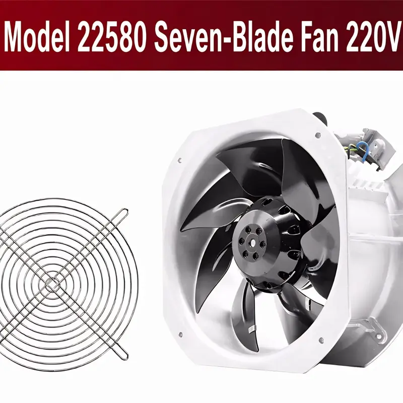
2026/09/30
Cement cabinets choke on dust. Learn the filter rule for an industrial cabinet cooling fan: G4/F7 media, IP rating, and pre-filter care.

2026/10/07
Right wall-mount height for an industrial axial exhaust fan: room volume, free clearance, brackets, and recirculation control.

2026/10/08
An ec motor fan links to BMS via Modbus, 0-10V and PWM for demand-based cooling, energy scheduling and automatic sensor-driven speed control.
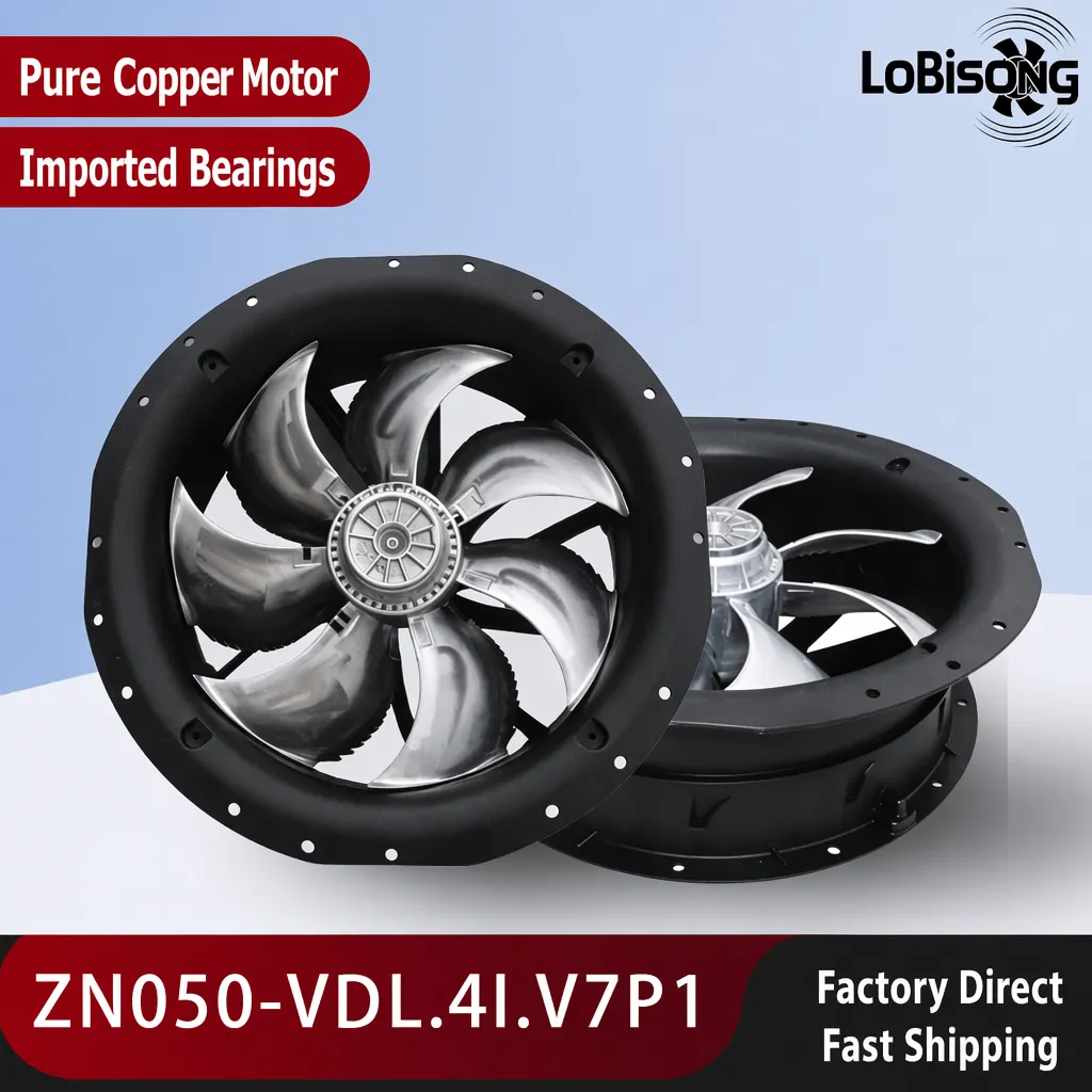
2026/10/06
A radial exhaust fan removes grease, fumes, and odors from food-processing workshops with capture velocity and hygienic washdown design.
2026/10/05
Learn antistatic treatment for industrial cabinet cooling fan in electronics workshops—ESD-safe housing, ionizable plastics, and cleanroom compatibility.
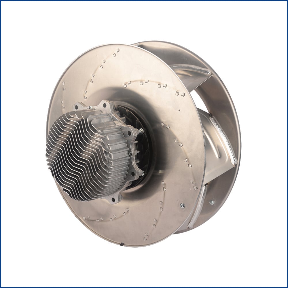
2026/10/04
Discover how a brushless dc servo delivers precise wind speed control for laboratory cooling fans with closed-loop PID feedback and laminar airflow.