EN
EN
What filter matching rule for dust proof cabinet cooling fan operating in cement factories
2026/09/30
Cement cabinets choke on dust. Learn the filter rule for an industrial cabinet cooling fan: G4/F7 media, IP rating, and pre-filter care.

2026/09/03
Why sensor choice decides whether the fan actually helps
A variable speed industrial axial fan tuned to the wrong signal either overcools the space or lets hot spots form, because the controller trusts a reading that does not represent the real load. Place the sensor by the cold supply and the fan slows too early, leaving the machine it serves still cooking. Place it where sunlight hits the probe and it speeds up for a phantom heat source. The mismatch shows up as noise complaints, wasted energy, or equipment that still trips, which is why the sensing scheme deserves the same engineering attention as the fan itself.
A single point sensor cannot see a large room, so one corner stays comfortable while another drifts toward limit. Without averaging or a second probe near the heat source, the controller reacts to the wrong place and the variable speed industrial axial fan hunts between speeds. That hunting wears the bearing and confuses the duty cycle, while the actual hot zone keeps climbing. A scheme that ignores thermal mass also responds too late, because by the time the air temperature moves, the solid parts beneath it have already overheated. Good sensing anticipates, poor sensing chases.
A manufacturing plant cooled its compressor room with a fixed louvered fan that roared all day and still let summer afternoons exceed the recommended temperature. The single thermostat sat near the door, far from the compressors, so it rarely saw the real load. Operators tolerated the noise because the alternative was a trip, yet the room swing between too hot and too cold showed the control had no sense of the machinery it protected.
The team installed a variable speed industrial axial fan with a PT100 probe mounted on the compressor discharge header, plus a second sensor at the room return. A controller averaged the two and staged the wheel against the warmer reading. The room settled into a narrow band, the compressors stopped tripping, and the fan ran quietly at partial speed most of the day. Energy dropped because the wheel no longer ran flat-out to satisfy a door-side thermostat, and maintenance gained a stable temperature they could trend.
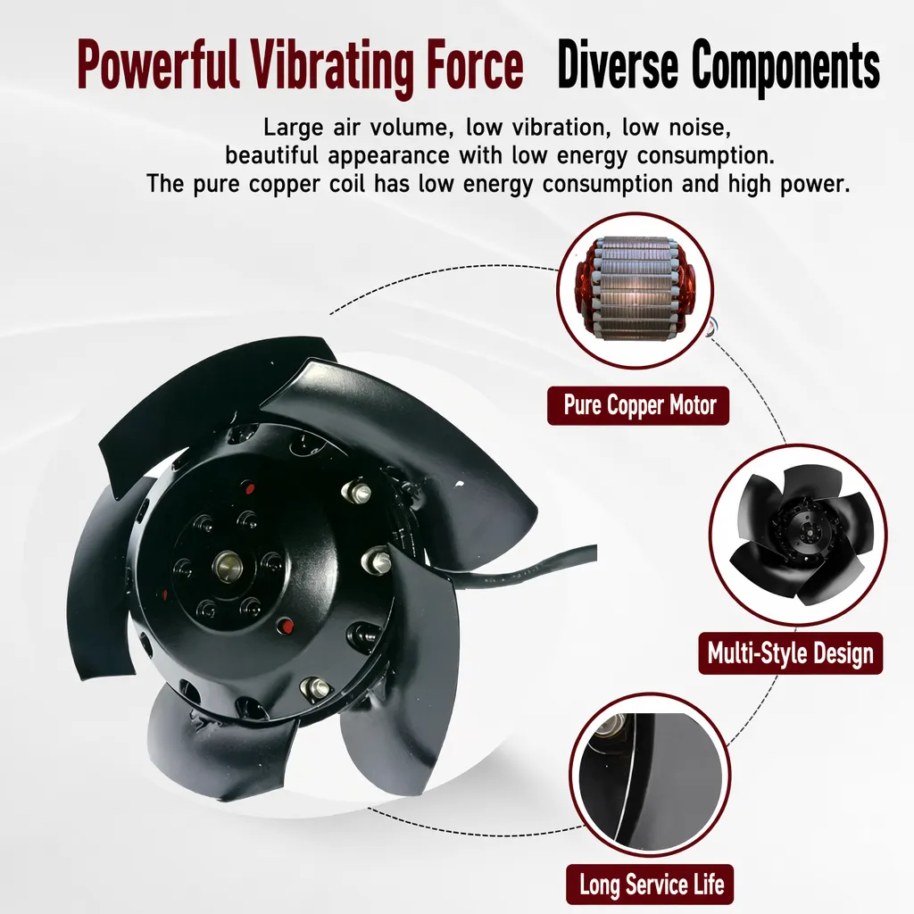
Sensor choice sets the accuracy and response the whole loop depends on. A PT100 RTD gives stable, linear readings suited to control, while a thermistor responds faster but drifts with age, and a thermocouple handles high ranges at the cost of needing cold-junction compensation. Placement matters more than the label: mount the probe on or near the heat source, shield it from direct sun and drafts, and route the signal away from motor cables to avoid electrical noise. The variable speed industrial axial fan only performs as well as the clean signal it receives.
The setpoint defines the target, the deadband prevents the fan from cycling on tiny fluctuations, and staging ramps speed in steps rather than lurching between off and full. Too tight a deadband makes the axial fan chatter; too wide lets temperature drift. A PID layer can smooth the response by weighing present error against its rate of change, which suits loads that swing. The logic should also cap minimum speed so the wheel never stalls in a stale corner, and the scheme must fail safe, spinning up if the sensor signal is lost rather than assuming all is well.
Temperature measurement leans on IEC 60751 for RTD accuracy and response, and ISA guidance helps define sensor location and loop tuning for trustworthy control. Electrical safety framing from NFPA 70E applies where the probe and controller sit inside live equipment, and regional machinery rules may require the fan to fail to a safe state. Specifying the variable speed industrial axial fan control against these references keeps the scheme measurable and comparable, instead of a guess patched together from catalogue notes.
Buyers should state the target temperature, the acceptable band, and where the real heat lives, then confirm the sensor type and its tolerance. Request the control logic description, the deadband setting, and the fail-safe behavior, because a fan that assumes a lost signal means safe is a liability. On commissioning, log temperature and fan speed together for a full duty cycle, and verify the wheel ramps with the load rather than hunting. A variable speed industrial axial fan earns its value only when the sensing scheme proves, over weeks, that speed tracks heat instead of noise.
A variable speed industrial axial fan turns a blunt on-off blast into a measured response that protects equipment and spares energy. The sensing scheme is the brain of that response, and getting it right is what separates a quiet, reliable room from one that swings between too hot and too loud.
Why does sensor placement matter for fan speed control?
The controller trusts the sensor it is given, so a probe by the cold supply or in sunlight drives the wrong speed. Mount the sensor on or near the real heat source, shield it from drafts and sun, and route the signal away from motor cables. A variable speed industrial axial fan performs only as well as the clean reading it receives, which makes placement the first engineering decision.
Which temperature sensor suits a fan control loop?
A PT100 RTD gives stable, linear readings ideal for control, while a thermistor reacts faster but drifts with age, and a thermocouple covers high ranges at the cost of cold-junction compensation. Match the type to the accuracy, response, and environment the loop needs, and verify tolerance against IEC 60751 rather than accepting a vague specification.
What is a deadband and why set one?
A deadband is the temperature window where the fan holds steady instead of reacting to every small fluctuation. Too tight a band makes the axial fan chatter and wear the bearing; too wide lets the space drift. The right deadband keeps speed stable through normal noise while still acting when the load genuinely moves.
How should multiple sensors be combined?
Averaging two or more probes gives a truer picture than a single point, especially in large rooms with one hot zone. Mount one near the heat source and another at the return, then let the controller act on the warmer reading. That prevents a comfortable corner from hiding an overheating machine the fan is meant to protect.
What happens if the sensor signal is lost?
A safe scheme fails by spinning the fan up, not by assuming the space is fine, because a lost signal should never mean less cooling. The controller should detect the fault, alert, and drive the fan to a protective speed. Specifying that fail-safe behavior upfront prevents a silent failure that lets equipment overheat unnoticed.
How is the control scheme validated after install?
Log temperature and fan speed together across a full duty cycle, and confirm the wheel ramps with the load instead of hunting between speeds. Check that the room holds the target band through the hottest part of the day, and review the trend over weeks. Only sustained tracking of heat, not a single good hour, proves the scheme works.
2026/09/30
Cement cabinets choke on dust. Learn the filter rule for an industrial cabinet cooling fan: G4/F7 media, IP rating, and pre-filter care.

2026/10/07
Right wall-mount height for an industrial axial exhaust fan: room volume, free clearance, brackets, and recirculation control.

2026/10/08
An ec motor fan links to BMS via Modbus, 0-10V and PWM for demand-based cooling, energy scheduling and automatic sensor-driven speed control.
2026/10/06
A radial exhaust fan removes grease, fumes, and odors from food-processing workshops with capture velocity and hygienic washdown design.
2026/10/05
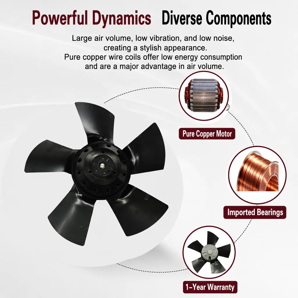
Learn antistatic treatment for industrial cabinet cooling fan in electronics workshops—ESD-safe housing, ionizable plastics, and cleanroom compatibility.
2026/10/04
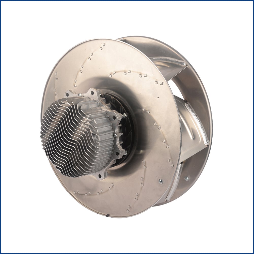
Discover how a brushless dc servo delivers precise wind speed control for laboratory cooling fans with closed-loop PID feedback and laminar airflow.